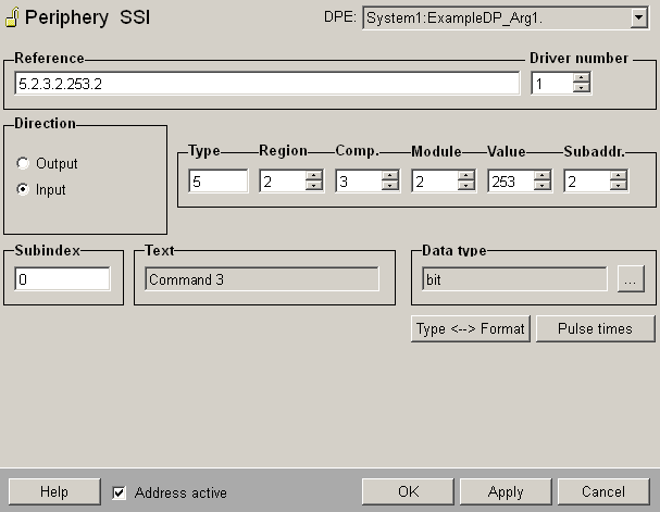
Panel for configuring the SSI driver
The peripheral address in WinCC OA is held in its own config. A separate hub config containing just the driver number is used to assign a data point to a driver and thus to an area of the system accessible from a particular remote head. At start-up the driver uses this number to register an interest in the data points that it is concerned with. If a hub config has not been created for a data point with a peripheral address, then this data point is assigned to driver number 1. The peripheral address config assigns a hardware address to a data point name; this address is coded as a character string.

Reference
This address has the following structure for SSI messages. The Option "Address active" is selected. An inactive address means, that there is no connection to the PLC (see Reference tables).
The address contains six items of information separated by ".":
-
Data type
-
Region number
-
Component number
-
Module number
-
Value number
-
Subaddress
Each piece of the address consists of a number (three figures maximum without leading zero). The data type is the data type configured for the expected message format. The subaddress should be 0 if the subAdrInUse entry in the configuration file is not set to "Yes".
Subindex
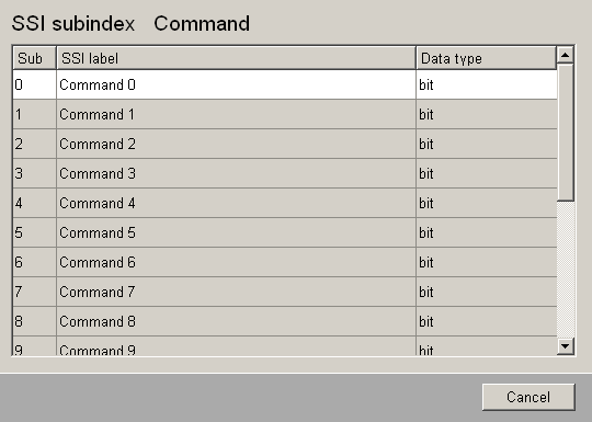
You can define a subindex to the data type. Which subindex is possible, you can see in the SSI Subindex panel. It opens by clicking "...".
Text
Displays the name of the SSI label, as displayed in the table of SSI Subindex panel.
Data type
Displays the according data format. For Command e.g. is it bit.
...
Click to the button "...", to display a panel with labels and data types for subindices. Which subindices and which data types are available depends on the format of the data type.

Data type <--> Data format
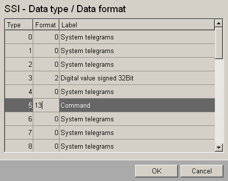
The data-type to data-format assignments are specified in the data point _SSI_DaDf_Table, which has 32 sheets for the different data types (0 to 31). Undefined data types have the initial value -1.

Pulse times
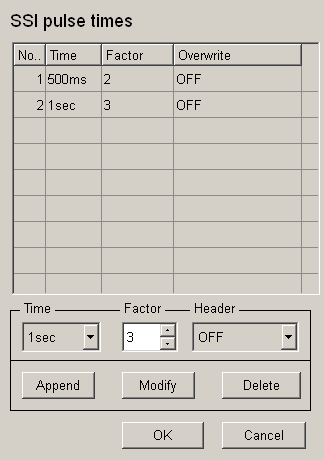
For the format 13 or 113 you can define pulse times by clicking the button "Pulse times". This opens the following panel:

Select the pulse time from the combo box Time, the Factor (1-31) and the Overwrite (OFF /ON). With "Append" you add the settings to the table, with "Modify" you modify a selected entry and with "Delete" an entry is deleted from the table. "OK" applies the new settings and the panel is closed, "Cancel" closes the panel without any changes.
Address active
The Option "Address active" is selected. The address is used by the driver (see Reference tables).An inactive address is existing, the attributes can be set or get, but the driver does not use these. That means for this data point you cannot send any values to the PLC, resp. receive from the PLC.
![]() Example
Example
The address of a data point with an integer data format (data format 2) is shown in the example. The project-related data type 11 is assigned to the integer format. The data point is assigned to the peripheral device with module number 20, value number 30 of component 21 in region 0. The correct address string then reads:
11.0.21.20.30.0
In addition for more complex data types (such as 16 separate messages), the subaddress of the peripheral address config can be set as an extra parameter for each element. The subaddress meaning is described under the individual message formats.


