Panel for configuring an RK512
The panel shown in the figure can be used for configuring an RK512 peripheral address, as used by the RK512 driver. The top panel field contains the name of the configured data point element. A combo box and two spin buttons appear below for configuring the peripheral address.
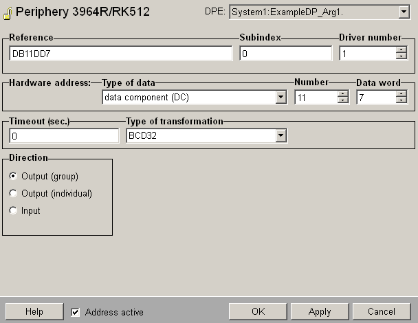
Address active
The Option "Address active" is selected. The address is used by the driver (see Reference tables).An inactive address is existing, the attributes can be set or get, but the driver does not use these. That means for this data point you cannot send any values to the PLC, resp. receive from the PLC.
Type of data
This combo box is used for selecting the data block type. All block types are supported apart from the absolute address type. If a type other than a data block or extended data block type is selected, the transfer direction is set automatically to input.
Table: Permitted data block types.
| Data block (DB) | Extended data block (DX) | Flags (M) |
|---|---|---|
| Input (E) | Output (A) | Timer (T) |
| Counter (Z) | Peripheral (P) | Extended peripheral (Q) |
| System address (BS) |
Number
The block number is set with this spin button. The value range for all block types is 0 to 255. Here it should be noted that PLCs do not always support the same value range for all block types.
Data word
This spin button is only displayed for data block and extended data block types. It is used for selecting a data word within a data block. The value range is from 0 to 255.
Subindex
WinCC OA allows several data points to be combined in an array. This array can be configured so that all the data is transferred between the PLC and driver in one message. The elements of an array are addressed using a subindex. The subindex is set with a spin button. If a data point does not belong to an array then the subindex is 0.
Transfer direction
The Transfer direction radio box sets whether a data point element is sent in the command direction (output) or in the message direction (input). For the command direction there is a further choice between group and single registration. For group registration all elements in an array are sent, while only the data point element concerned is sent for single registration. If input has been selected, another radio box appears beside this one, where the receive mode can be set.
Response time
A time must be entered in the Timeout field on the left of the panel. This is the time that must be waited for peripheral messages before declaring invalid ("Original value is invalid", attribute "original..invalid"). The timeout is specified in seconds. If the timeout is 0 then this action is disabled.
Data format
Using the Data format combo box on the right of the panel, the data conversion type between PLC format and WinCC OA format is specified. All the data formats are listed in
Table 3. It should be noted that not all the data formats are possible for all the data block types. A summary of which data formats are possible for which data block types is given in the appendix.
Low level old/new comparison
This option can only be selected if the transfer direction has been set to input. If this option is selected then data is only sent if there is a change. The comparison is performed on raw data without any conversion.
Receive mode
For transfer in the message direction, this radio box can be used to select whether the driver receives messages spontaneously, or by means of a single query or polling.
Polling mode settings
The additional settings for the polling mode are described below.
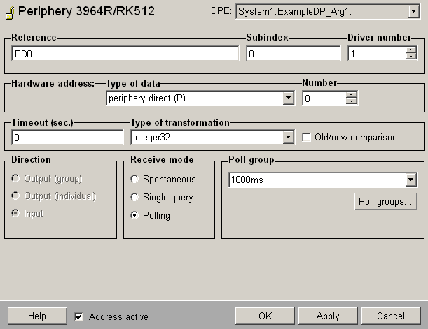
Poll group
Choose already existing poll groups. If there are no poll groups available you have to create them with the specific polling parameters in a separate panel. The panel is opened by clicking on the Poll groups... button (see Poll groups for more information on poll groups and polling parameters).
Since transmission over a serial interface is quite slow, the polling times should not be set too short. What times are still achievable depends on the set baud rate, the number of polled data points and the location of their hardware addresses.


