Example for the DNP3 Driver - Establishing communication
This chapter contains stepwise instructions for establishing a communication to the DNP3 driver.
Automatic general query while starting the driver
The DNP3 driver executes a general query while establishing the connection. This can be deactivated with the config entry integrityPollAtStartup = 0.
Configuration file of the DNP3 driver
#A TCP connection does not require config entries
#in the [dnp3] section
#The serial connection requires the config entry
# deviceSerial, for example:
[dnp3]
  deviceSerial = "IF1" "Com1" "9600,e,8,1"
For detailed information on config entries, see Possible Config Entries [dnp3].
-
Configure the device (outstation) in the panel “DNP3 Configuration” (see Configuration of the DNP3 Driver). TCP connection:
Enter in the Host field the computer name/IP address, in the Port field the server port number and in the LA field the link address to the outstation (see example in figure "DNP3 configuration TCP" below). Serial connection:
Enter in the Device field the name of the interface (e.g. IF1) and in the LA field the link address to the outstation (see example in figure "DNP3 configuration serial" below).
Figure 1. DNP3 configuration panel 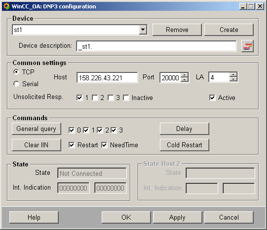
Figure 2. DNP3 configuration serial 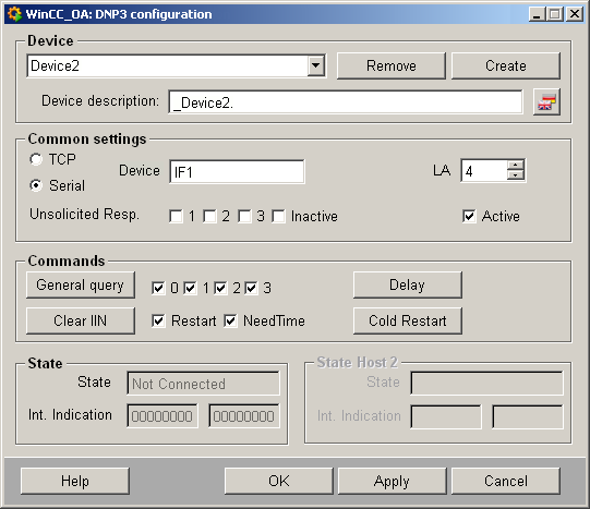
-
Add the DNP3 driver manager with the driver number 1 to the project console and start it. The WCCILsim simulator must not be running!
WCCOAdnp3 -num 1 -
After successful connection establishment to the server, a message is written to the log viewer (e.g. from the client system):
WCCOAdnp3 (1), 2008.08.06 09:26:05.428, SYS, INFO,
4, Connected to, (SYS: 1 Event -num 0 CONN: 1)
WCCOAdnp3 (1), 2008.08.06 09:26:05.537, SYS, INFO, 156, Driver initialization finished. -
Configure the peripheral address to your outstation for "Device 1" (see Defining the Peripheral Addresses of the DNP3 Driver).
In this example a data point element is used, with which analog values are received (DNP3 AnalogInput) and binary values are sent (DNP3 Binary Input). This element contains the _address (peripheral address) and _original (transmission of data) configs.
-
Define peripheral addresses for an binary input and a binary output (see screenshots below). For the binary input the Function field is empty, as this is clearly for the driver which it has to use for read. The variation is set, for example, to 2, because the value should be read as 16 bit value with status flags. For the output the function 5 is set. This corresponds to "Direct Operate". Thus, the value is configured without prefix. The variation is 1, whereas this is a 32 bit value.
Figure 3. Address configuration panel for a binary input 
Figure 4. Address configuration panel for an analog output