Control model implementation in WinCC OA
To reduce the number of peripheral addresses required, the WinCC OA implementation maps the attributes of the data structures SBOw and Cancel to one virtual address. Furthermore, User Bits are facilitated for transmitting information required to distinguish between different services and to transfer additional information. The WinCC OA 61850/61400 client interprets the received value and bit pattern and creates the data structure necessary to call the required service.
By default the bits for configuring a control operation are located at User Byte 1. You may use the config entry userByteCommandMode to map these bits to any other User Byte. For selecting a specific service the setting of the first two bits is relevant. In the following example we will only regard these two bits. For a complete description of the command byte please refer to the table below.
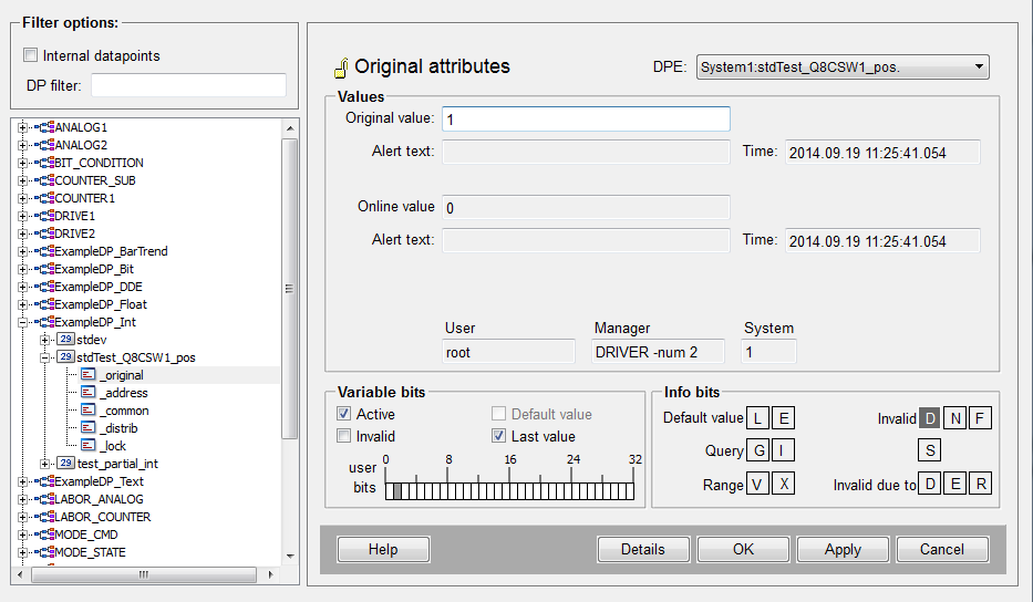
The different operations are illustrated in the example of changing the position of a currency switch (CSWI) with the physical address protectionDevice.TestDevice1CTRL/Q1CSWI1$ST$Pos. The addresses used in the example are as defined by the IEC standard.
The value to operate this switch has the physical address
protectionDevice.TestDevice1CTRL/Q1CSWI1$CO$Pos$Oper$stVal
The data type of stVal depends on the controllable object. In this example it is BITSTRING which can be mapped to e.g. an INTEGER data point element. If the IEC data type of ctlVal is an analog value, the actual data type might be integer or float. In this case the peripheral address would be:
-
Integer: protectionDevice.TestDevice1CTRL/Q1CSWI1$CO$Pos$Oper$stVal$i
-
Float: protectionDevice.TestDevice1CTRL/Q1CSWI1$CO$Pos$Oper$stVal$f
Virtual Addresses
The IEC 61850 driver uses the following virtual addresses:
-
protectionDevice.TestDevice1CTRL/Q1CSWI1$CO$Pos$Oper$operVal - this address is used for sending select and cancel commands
-
protectionDevice.TestDevice1CTRL/Q1CSWI1$CO$Pos$Oper$error - this address is used for receiving error and response codes
-
protectionDevice.TestDevice1CTRL/Q1CSWI1$CO$Pos$Oper$addCause - this address is used for receiving additional information on errors
Please note that these addresses are virtual addresses used by the WinCC OA IEC 61850 client. They DO NOT exist in the device and therefore do not appear in the browse result. Suggestion: Copy the address string from protectionDevice.TestDevice1CTRL/Q1CSWI1$CO$Pos$Oper$ctlVal to the address configs of the respective DPEs and manually change the last element of the string.
Configuration requirements:
operVal must get the same data type as ctlVal and must be configured as output address.
error and addCause must be of type INT32 and must be configured as input addresses with receive mode unsolicited. Since these addresses do not exist in the device they MUST NOT be used in any dataset. The values written to these DPEs are read from the response which the driver receives from the device after sending a command or in case a command runs into any kind of timeout.
It is recommended to monitor these virtual addresses since they give precise information on how a device responds to a command issued by the client. By reading the response codes for object selected (50), operation cancelled (51) and command successfully issued (100) an operator can immediately see that the respective command was issued properly.
Configuration Attributes
The attributes listed below characterize a command.
Type of Control Model (ctlModel)
The type of the control model is defined by the value of the attribute protectionDevice.TestDevice1CTRL/Q1CSWI1$CF$Pos$ctlModel. Following values are allowed:
| Operation | Value |
|---|---|
| Direct operation with normal security | 1 |
| Select before operate with normal security | 2 |
| Direct operate with enhanced security | 3 |
| Select before operate with enhanced security | 4 |
For reading this attribute it must be part of a dataset or a poll group.
SBO Time-out (sboTimeout)
The time-out for the Select before operate commands is defined by the value of the attribute protectionDevice.TestDevice1CTRL/Q1CSWI1$CF$Pos$sboTimeout.
This value determines how long a command is operable after it has been selected.
For reading this attribute it must be part of a dataset or a poll group.
Status Selected (stSeld)
This attribute may be monitored to find out if a Select request was successful. For this you need to read the address protectionDevice.TestDevice1CTRL/Q1CSWI1$ST$Pos$stSeld.
For reading this attribute it must be part of a dataset or a poll group.
Determine if a request was successful
To determine if an object was successfully selected by a specific client it is necessary to monitor the element OperError. Please refer to response codes for details.
Direct Control with normal and enhanced security
Bit pattern: 00
Operation: Write the required value to protectionDevice.TestDevice1CTRL/Q1CSWI1$CO$Pos$Oper$stVal.
The distinction between normal and enhanced security is done by the configuration of the peripheral device.
Select before operate control with normal security
Bit Pattern: 01
Sequence of Commands:
-
Write any value to protectionDevice.TestDevice1CTRL/Q1CSWI1$CO$Pos$Oper$operVal.
-
Wait for protectionDevice.TestDevice1CTRL/Q1CSWI1$ST$Pos$stSeld to transition to TRUE or for receiving the value 50 at the element protectionDevice.TestDevice1CTRL/Q1CSWI1$CO$Pos$Oper$error
-
Write the required value to protectionDevice.TestDevice1CTRL/Q1CSWI1$CO$Pos$Oper$ctlVal. If the device accepts the command, the value 100 is written to protectionDevice.TestDevice1CTRL/Q1CSWI1$CO$Pos$Oper$error
Select before operate control with enhanced security
Bit Pattern: 11
Sequence of Commands:
-
Write the required value to protectionDevice.TestDevice1CTRL/Q1CSWI1$CO$Pos$Oper$operVal.
The service actually called is SelectWithValue
-
Wait for protectionDevice.TestDevice1CTRL/Q1CSWI1$ST$Pos$stSeld to transition to TRUE or for receiving the value 50 at the element protectionDevice.TestDevice1CTRL/Q1CSWI1$CO$Pos$Oper$error.
-
Write the required value to protectionDevice.TestDevice1CTRL/Q1CSWI1$CO$Pos$Oper$ctlVal. If the device accepts the command, the value 100 is written to protectionDevice.TestDevice1CTRL/Q1CSWI1$CO$Pos$Oper$error
Time activated operation
For initiating a time activated operation use any of the operations described above but also write the time, the operation shall be executed to protectionDevice.TestDevice1CTRL/Q1CSWI1$CO$Pos$Oper$operTm.
Cancel
Bit Pattern: 10
Operation: Write any value to protectionDevice.TestDevice1CTRL/Q1CSWI1$CO$Pos$Oper$operVal. If the device accepts the cancel command the value 51 is written to protectionDevice.TestDevice1CTRL/Q1CSWI1$CO$Pos$Oper$error.
Response
For receiving the response from the device you may configure the addresses described in the following. These addresses are also virtual addresses introduced by the WinCC OA implementation. You cannot find these addresses on your peripheral device. Configure these addresses for unsolicited communication.
The response codes are transmitted by a service specific to the control model mechanism. The following two addresses must be configured for unsolicited communication but most not be part of any dataset.
Error codes
Configure: protectionDevice.TestDevice1CTRL/Q1CSWI1$CO$Pos$Oper$error
In case of an error you will receive the IEC error codes for any operation performed. This address is also used for monitoring positive responses. For further information please also refer to error codes.
Additional information
Configure: protectionDevice.TestDevice1CTRL/Q1CSWI1$CO$Pos$Oper$addCause
This address will only be written if one of the enhanced modes is used. For further information please refer to addCause
CommandMode type definition for bits (1- 8)
| Bits | Description | |||||||||||||||
|---|---|---|---|---|---|---|---|---|---|---|---|---|---|---|---|---|
| Bit1, Bit2 |
These two bits represent the type of service in command bits.
|
|||||||||||||||
| Bit3, Bit4 |
These two bits represent check condition in command bits.
|
|||||||||||||||
| Bit5 |
This bit represents the test status. The service parameter Test indicates if the client sends a control service for test purposes only. True indicates that the test is performed. All service requests belonging to one control sequence must have the same test status. |
|||||||||||||||
| Bit6 |
This bit represents the automatic mode status. TRUE: automatic mode is set FALSE: automatic is not set This bit modifies the originator category, see also origin.orCat. |
|||||||||||||||
| Bit7 |
This bit represents the maintenance status. TRUE: Maintenance is set FALSE: Maintenance is not set If this bit is set, origin.orCat settings are ignored and the originator category is set to maintenance. |
|||||||||||||||
| Bit8 | Bit 8 - periphBlkd indicates "No action" to the client and may be used for testing or engineering. |


