Example of a Building Automation Project
In order to re-illustrate all of the steps for a successful creation of a building automation project in WinCC OA, the following example has been prepared. In most cases, the individual steps relate to the chapters of this documentation.
The aim of this example is to extend the already existing example panel "Testpanel_Symbs.pnl" to a new BACnet device and its objects. The device information is taken from an EDE file template (offline engineering).
This example is comprised of the following steps:
 Example of a Building automation project
-
Embedding the object libraries
To implement this example, it is necessary to embed the Standard Object Library and the BACnet Object library into an already created/existing WinCC OA project (see Embedding the Object Libraries).
-
Download of the EDE file templates
This example is based upon the device information from an EDE file (offline engineering). The EDE file EDEexample_EDE.csv, which is used, can be downloaded for free (see Offline Engineering). Download this EDE template package and save it in the directory \data of the WinCC OA project.
-
Example panel
Along with the WinCC OA BACnet package, two example panels are supplied. These show a storage site - one with simple symbols and one with technological symbols. In this example, the panel "Testpanel_Symbs.pnl" is used. Open this from the directory <C:\Siemens\Automation\WinCC_OA\3.18\ _installation_directory>\BACnet_<version>\panels.
Figure 1. Example panel "Testpanel_Symbs.pnl" 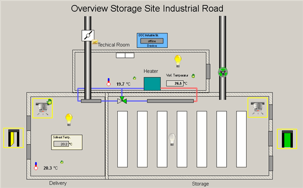
This panel shows symbols that represent fixtures (lamps, fans, thermometers, etc.) in a storage site. In reality these fixtures send information about their value/state to the BACnet device, from which the device information from Engineering Explorer is uniquely read and updated (online engineering). These symbols were already referenced as objects of the example device "DDC IndustrieStr." (Device 6789).
-
Creation of the device from the EDE
file
-
Open Engineering Explorer via WinCC OA System Management -> BACnet tab
-
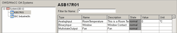
Search the EDE file EDEexample_EDE.csv for devices (see Browse for Devices).
The following devices are found in the EDE file:
Figure 2. Figure: Devices in EDE file 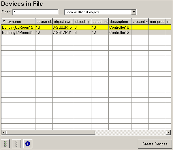
-
Highlight the device with object name "ASB17R01".
-
Create the device in WinCC OA by clicking on the "Create Devices" button.
-
Click on the
 button, so that the tree view is updated and the newly
created device becomes visible in Engineering Explorer.
button, so that the tree view is updated and the newly
created device becomes visible in Engineering Explorer.
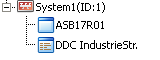
The following tree structure should now be displayed in Engineering Explorer:
-
-
Importing the objects of the
created device
-
Browse the EDE file EDEexample_EDE.csv for new objects for the device ASB17R01 (see Browsing for a device (offline)).
The following objects are found in the EDE files for this device:
Figure 3. Objects in the EDE file 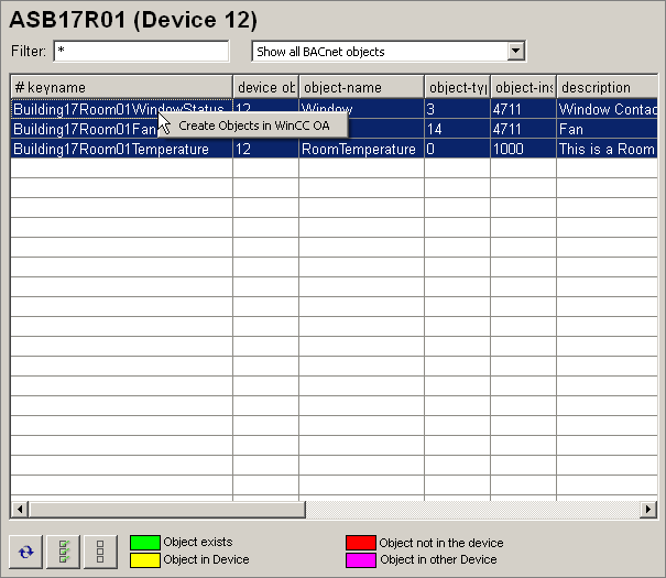
-
Highlight all the found objects found by clicking on the
 button.
 -
Create the found objects in WinCC OA by clicking on the "Create Objects in WinCC OA" option of the context menu (right mouse-click) of the tabular view.
-
-
Adapting the
properties of the new objects in the faceplate
As the current value of every new object from the EDE files is 0 by default, these must be changed manually in the corresponding faceplates.
RoomTemperature
-
In the tree view of Engineering Explorer, select the device ASB17R01, so that the three created objects are listed in the table on the right.
-
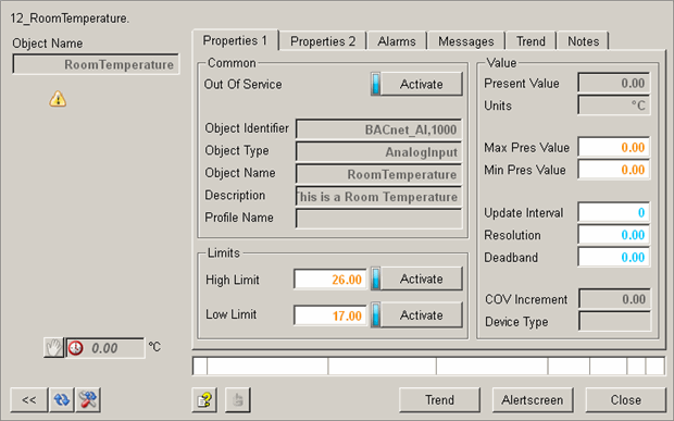
Open the faceplate of the object "RoomTemperature" by a double-click on the corresponding row of the table.
-
Open the extended view of the faceplate by a click on the
 button.
The following view should now be seen:
-
In the faceplate, change the value of the property Max_Pres_Value to 30.00, and confirm by pressing the enter key.
-
In the faceplate, change the value of the property Min_Pres_Value to 10.00, and confirm by pressing the enter key.
-
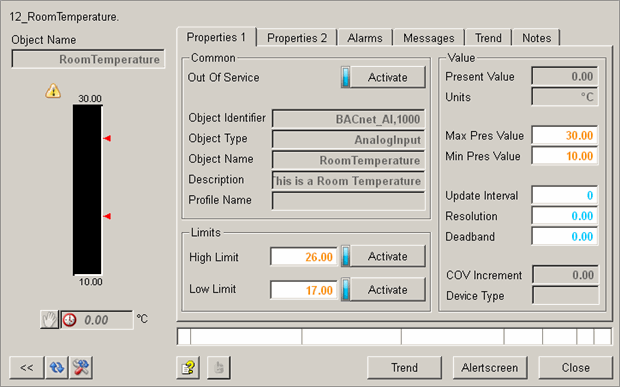
Close and then reopen the faceplate.
The following view should now be seen:
-
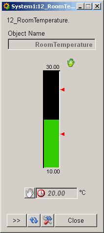
Activate "Out Of Service" mode by clicking on the "Activate" button in the "Common" faceplate area.
-
Change the present value (Present_Value) of the object by clicking on the manual value symbol
 (hand value) on the
left side of the faceplate and subsequently clicking on the input field
next to the symbol.
(hand value) on the
left side of the faceplate and subsequently clicking on the input field
next to the symbol. -
The value input panel is opened (see Value input panel). Enter the value 20 and confirm by clicking "Apply".
-
Deactivate "Out Of Service" mode.
The faceplate should now appear in its final state as shown:
Window
-
Open the faceplate of the object "Window" by a double-clicking on the corresponding row of the table.
-
Open the extended view of the faceplate by a click on the
button. -
Activate "Out Of Service" mode by clicking on the "Activate" button in the "Common" faceplate area.
-
Click on the
button to activate the manual value (hand value). -
Click on the "On" button to switch on the window contact.
-
Deactivate "Out Of Service" mode and close the faceplate.
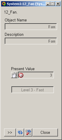
Fan
For the multi-state object "Fan", it is first necessary to define the states that the fan can accept. This happens in the WinCC OA PARA.
-
Open the faceplate of the object "Fan" by a double-clicking on the corresponding row of the table.
-
Open the extended view of the faceplate by a click on the
button. -
Click on the
 button in the "State Texts" area on the "Properties 1"
tab and enter the text "Level 1 - Slow".
button in the "State Texts" area on the "Properties 1"
tab and enter the text "Level 1 - Slow". -
Add 3 further texts:"Level 2 - Normal", "Level 3 - Fast" and "Off".
-
Click on the
 button to apply the list with the state texts to the
WinCC OA project.
button to apply the list with the state texts to the
WinCC OA project. -
The Number of States automatically changes to 4.
-
Activate "Out Of Service" mode by clicking on the "Activate" button in the "Common" faceplate area.
-
Click on the
button to activate the manual value (hand value). -
Click on the input field below the "Present Value" to open the value input panel (see value input panel).
-
In the value entry panel, the states defined previously correspond to the entries 1 to 4. Enter 3 for the state "Level 3 - Fast".
-
Deactivate "Out Of Service" mode.
The faceplate should now appear in its final state as shown:
-
-
Introducing the objects into the
example panel
The panel described in step 3 can now be completed with Device ASB17R01 and its 3 objects.
The technical room should be enlarged and extended by a separate control area for the Server that exists there.
For better orientation with the positioning of the device and the objects, the example panel should eventually look as shown below:
-
Extend the technical room by extending the left wall to the length of the delivery room.
-
Open the BACnet symbol catalog via the WinCC OA menu View -> Catalogs -> <C:\Siemens\Automation\WinCC_OA\3.18\ _installation_dictionary>\BACnet_<Version>
-
Drag the symbol "Device" on to the example panel. Position it above the wall of the technical room on the left hand side.
-
The "Reference parameterization" is automatically opened:
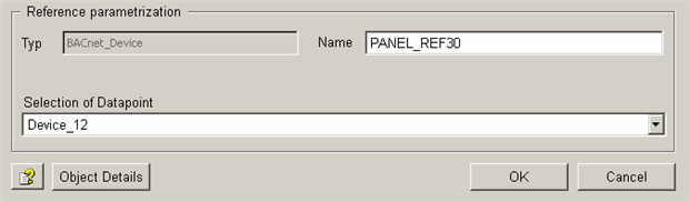
-
From the combo box "Selection of Datapoint", choose Device_12. The name of the datapoint is given automatically according to the property Object_Identifier of the object. The remaining settings remain unchanged.
-
Confirm the Reference parameterization by clicking "OK".
-
Following the same principal, position the objects in the example panel:
-
Object "RoomTemperature" - Symbol: Temp_2; Datenpunkt: RoomTemperature
-
Object "Window" - Symbol: Mini_BI; Datenpunkt: Window
-
Object "Fan" - Symbol: Fan_1; Datenpunkt: Fan
-
-
Example for the manual triggering of an alarm for the object
RoomTemperature
-
Open the newly changed example panel in the QuickTest module.
-
Right click on the symbol for "RoomTemperature".
-
The context menu is opened. Choose the "Para" option.
-
The WinCC OA PARA of this object is opened.
-
Change the value of the datapoint element RoomTemperature.alarm.Event_State.._original to 1.
-
Apply the changes and close the WinCC OA PARA.
-
The click frame of the symbol in the connected panel is now flashing.
-
Left click on the symbol.
-
The faceplate of the object/datapoint is opened.
-
In the extended view of the faceplate, the recently triggered alarm will be displayed at the bottom.
-
This can either be directly acknowledged here, or in the "Alarm" tab.
-


