SINAUT Driver Configuration
Open the configuration panel of the SINAUT driver via the system management panel to configure the Master TIM connection in WinCC OA.
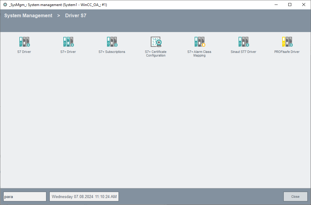
Click on the Sinaut ST7 Driver button.
Configure in the following panel a peripheral device/peripheral connection. In a redundant project the host settings and state information are displayed separately, next to each other for every server.
The configuration panel of the SINAUT driver is divided into the following areas.
Connection
A click on the "Create“ button opens a dialog to create a new SINAUT data point/device with basic setting (in a redundant project a data point <connection_name+_2> will be created automatically for the redundant connection). After creating a new device, other parameter may be set for this device. These will be saved in the internal data point type “_SinautConn”.
Click on "Apply" to create the connection data point containing the parameters or on "OK" to create the connection data point containing the parameters and to close the configuration window afterwards. Click on "Cancel" to close the configuration window without creating the connection data point, if not already done.
Select from the combo box the connection name, if you want to change the configuration of a created connection. Disable the "Active" checkbox, change the configuration, click on “Apply” to save the changes an re-tick the "Active" checkbox. Once a connection data point is created, it can be used by the driver (no reboot required).
Clicking the button “Remove” you can remove a selected device.
In the text flied “Device description” you can enter or change the description of a created connection (default “_<device_name>").
Configuration
Tick the “Active” check box to activate the connection to the peripheral device. A created and configurated connection can be deactivated in this configuration panel at any time. The connection data point will not be removed and can be re-activated anytime. The state indications changes from "Connected" to "Not active" when the connection is deactivated.
Enter in the "Timeout (ms)" input field the timeout for the connection establishment in milliseconds.
Local
Please enter for
-
"Node-Number" the SINAUT node number of the driver for this connection (1 - 32767).
-
"Rack" the rack number of the driver PC (0-255).
-
"Slot" the slot number of the driver PC (0-255).
-
"Resource" the connection resource ID of the driver PC.
How to determine these data from the Simatic project in NetPro is described in the paragraph Determination of the rack numbers, slot numbers and connection resource IDs.
Remote (Master TIM)
Select in the "IP:" input field using the spin buttons an IP address of the Master TIM or enter this directly. The IP address must equal to the IP address from the SINAUT project settings.
Please enter for
-
"Node-Number" the SINAUT node number of the Master TIM for this connection (1 - 32767).
-
"Rack" the rack number of the Master TIM (0-255).
-
"Slot" the slot number of the Master TIM (0-255).
-
"Resource" the connection resource ID of the Master TIM (0-255).
How to determine these data from the Simatic project in NetPro is described in the paragraph Determination of the rack numbers, slot numbers and connection resource IDs.
Commands
By clicking on the "General query“ button a general query is executed for the selected connection. The next received data will be sent to WinCC OA (without consideration of low-level-comparison and smoothing). A general query is automatically executed after connection establishment or a redundancy switch.
By clicking on the "Time synchronization" button a telegram is sent to the Master TIM in order to synchronize the time.
State
The "State" area displays information about the current device.
The "State" field informs about the peripheral connection state to the Master TIM. Thereby four states are possible:
-
"Not connected" - lost connection to the Master TIM, e.g. Master TIM has been disconnected from network
-
"Connected" - connected to the Master TIM
-
"General Query" - general query is executed
-
"Not active" - Master TIM is set to inactive
The "Error" field displays the last error code that occurred for this connection.
Determination of the rack numbers, slot numbers and connection resource IDs
The rack numbers, slot numbers and connection resource IDs of the local systems and of the central TIM have to equal to these from the Simatic project. Open the Simatic project in Simatic NetPro.
Determination of the rack number of the local system
Open the hardware configuration of the locale system. In the header of the rack window the needed rack number of the local system is displayed.
Determination of the other needed data
In order to determine the slot number and the connection resource ID of the local system and the rack number, slot number and connection resource ID of the central TIM System, the following steps have to be performed:
-
Open the application information of the local system by double-clicking the specific area in NetPro.
-
Open the properties of the S7 connection by double-clicking the Partner ID.
-
Click on the "Address Details" button in the properties of the S7 connection. The address details with the needed information on rack number, slot numbers and connection resource IDs are opened: