
System architecture
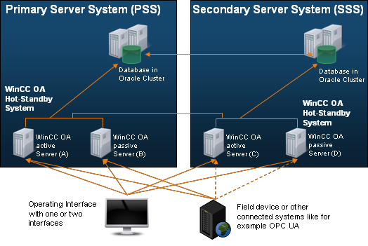
The functionality of the Disaster Recovery System is based on two WinCC OA standard functions. These are WinCC OA Hot Standby Redundancy and the WinCC OA supported Distributed Systems, that are used between the PSS and the SSS.
Connection
All PSS and SSS servers are connected via LAN or WAN (TCP/IP protocol).
Normal operating mode
In normal operation, the PSS system supports the connection to the field devices (or control center with OPC UA port) and communicates all values to the SSS via the Control Manager.
On the work station, there are two possibilities:
- Two WinCC OA user interfaces are started. One has a connection to the PSS and the other to the SSS. The management system user interface runs in the foreground. All panel switching from this UI is automatically communicated to the other UI (this is only visible to the user if the connection to the PSS is down), so that the same image is always displayed on both UIs.
- A WinCC OA user interface that supports the connection to the PSS is started or a WinCC OA user interface is started that supports the connection to the SSS. The decision is made by the user after the connection to the active system is lost. The user makes the decision after losing connection to the active system. The user receives a notification when the other system becomes passive again and the user interface must then be opened with the connection to the other system.
PSS (Primary Server System)
The PSS consists of a redundant WinCC OA project in which various drivers and control managers are controlled and thus maintain and further process the current data of the field devices (or master control center with OPC UA port). The hot standby concept dominates between the two servers within the primary server system.
For more information on WinCC OA redundancy, see chapter Redundancy, Basics.
SSS (Secondary Server System)
The SSS is intended for management in the event of a total failure of the PSS or maintenance of the PSS. It is also a redundant WinCC OA project that has the same configured drivers and control managers as the PSS. In simple terms, it is a mirror image of the PSS.
Normally, the SSS has no connection to the field devices (Master Control Stations) and does not perform any calculation operations (except for WinCC OAinternal calculations such as fault quantifiers, compressions, etc.). Nevertheless, the process data is available on this system with a very small delay, since the values of the datapoints and the alert status are continuously transmitted from the PSS using the WinCC OA distributed systems mechanism.
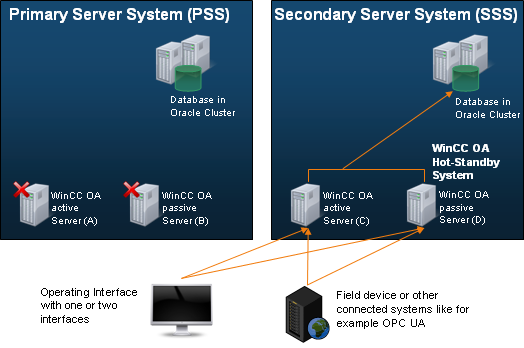
If both computers of the PSS fail, the servers of the SSS take over the complete monitoring and control of the project. For the user, this means only a brief interruption in the operation of the application before the SSS takes over control, establishes the connection to the field devices (or master control stations) and provides the current values for the user.
When the failed server on the PSS resumes operation, the disaster recovery system performs reverse data migration. Note that an automatic fallback from SSS back to PSS only occurs when the Fallback from SSS to PSS option is enabled (see Configuration - Step 6 - Activation). During such a fallback switchover, the WinCC OA managers on the PSS are restarted and current online values can be synchronized from the SSS to the PSS. Whether online values are actually synchronized depends on the configured synchronization direction in the Online Values panel (Configuration - Step 2). If the synchronization type is set to Synchronization from PSS to SSS (the default), online values are not synchronized from the SSS to the PSS during fallback. To enable reverse synchronization, select Synchronization from the active to the passive system or Synchronization in both directions.
Historical data is not synchronized automatically during fallback. Historical synchronization must be triggered manually using the Historical Synchronization panel. For more information, see RDB Archiving.
If the connection between the PSS and the SSS has failed, both systems are active, and it must be assumed that the other system has failed. In this case, an alert is triggered for the loss of connection of the DIST manager. You can work on both systems and both systems establish a connection to the field devices.
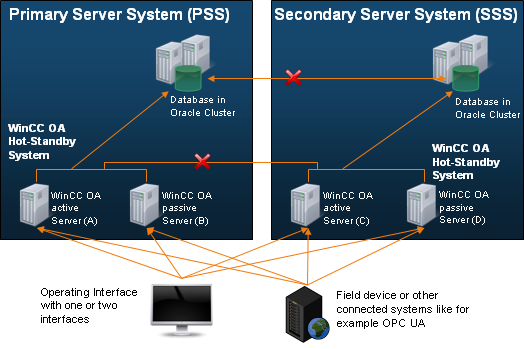
The disaster recovery system can cover both cases. Data synchronization after a connection interruption between the PSS and SSS takes place automatically during the next synchronization cycle or can be repeatedly activated manually via the operator interface after the synchronization alarm has been triggered. Data synchronization after a connection establishment takes place from the PSS (master) to the SSS (slave).