
Master Datapoints
It is recommended to use master datapoints wherever several devices of the same type are modeled through datapoints. Even if we only have a pump in our example, we still need two level measurements and three valves that should be configured. In a real plant, hundreds of devices of a device type are often used. Therefore, the following steps are required.
Instead of configuring the controlfunctionalities (configs) for each element of every DP individually, you can select and configure the configs for the whole device class at once.
First you have to create the data structure for the further datapoint types. Create the structures for the datapoint types GS_LEVEL and GS_VALVE corresponding to the following tree views (see the chapter Modeling of Datapoint Types).
After this, select the datapoint type GS_LEVEL from the tree view and select the "Create master datapoint" entry of the context menu [rightMouseClick]. The master datapoint will now be created automatically: the naming corresponds to the data point type, however the prefix "_mp_“ (for a master data point) is added.
The master datapoint is a unit with the datapoint type. For a master datapoint, the configs are specified for the instances, whereas the datapoint type specifies the structure, naming and data types for all instances. There are properties that are configured consistent fixed for all instances at the master datapoint. Other properties have to be set different depending on the device. Therefore, there are different types of configs for master datapoints. Since configs of master datapoints already contain specific settings or are able to represent combinations of several configs, they are called "PowerConfigs" in order to differentiate them from the normal configs.
WinCC OA can be used with individually created datapoint instances and therefore without a master datapoint, as well as with predominantly similar data point instances (with a master datapoint). If you delete an existing master datapoint of a datapoint type, the type irrevocably loses a part of its object properties - if necessary the existing datapoints (instances) still work but are separated from the inheritance. Therefore, always work with master datapoints.
In the next step you specify a value range monitoring as well as an analog alert handling for all level measurements of the data type GS_LEVEL . Therefore, open the master datapoint and select the following configs on the leaf element _mp_GS_LEVEL.level [right mouse click] > Add PowerConfig.
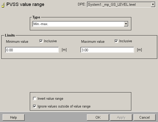
In the following figure the PowerConfig "WinCC OA Value range" was selected for the value range. This is necessary since the tanks and reservoirs always have different heights and cubic capacities. Therefore, you have to enter the limit values for the level individually for each device (datapoint/instance). The range limits which are configured here, are just a one.time preconfiguration.
The setting "WinCC OA value range" - fixed would have meant that all .level datapoint elements of datapoint type GS_LEVEL have numerically the exact same value range. For example, this would be used for a percentage value of a flap or a standardized rotation speed.
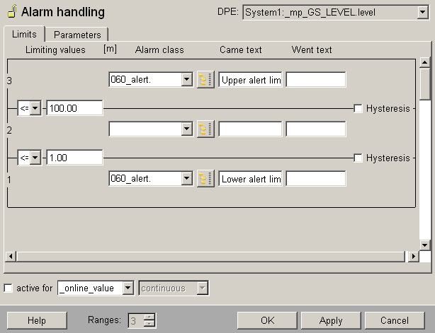
You can also define the alert handling - make the settings as shown in the figure above. By selecting an alert handling with three ranges, it's possible to set different limit values for higher and lower alerts for each datapoint later.
Fixed would have meant that you can configure an arbitrary alert handling for a master datapoint later and this would be applied identically to each .level element for each datapoint of type GS_LEVEL. This means the same limit values would be monitored for each level and an exceedance would always cause an alert of the same priority.
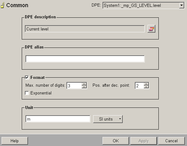
In order to set a meaningful formatting and unit for all future level measurements, add a third power config "Var: Description: Fixed: Unit (and Format)" as shown in the figures above. This means that you can configure a different description for each datapoint (for each device) but the unit and the format for the number representation will be inherited from the setting of the master datapoint.
The figures above show the dialog for the power config selection after completing the settings - the selected option of the PowerConfig is shown behind the type of the PowerConfig. Confirm with OK. Confirm also the displayed hint that you have to configure these PowerConfigs subsequently.
Apply the settings as shown in the following figures in your project.
After completing the entries with OK in the last parameter dialog, you have to apply the settings. Click on Yes in the confirmation dialog to apply the settings.
The settings are also applied for already existing datapoints. Therefore, changes for a master datapoint can be applied to the instance datapoints.
Now the next step would be creating instance datapoints for the tank 1 and for the tank 2. Subsequently the properties that are "variable adjustable for the instance" would be configured. These steps are described detailed in the chapters Creating datapoints with the database editor PARA and Configuration of the PowerConfig Settings for Data Points. First, you will, however, prepare also the last datapoint type GS_VALVE using a master datapoint.
Proceed correspondingly when configuring the PowerConfigs for the datapoint type GS_VALVE.
-
Create a master datapoint of type GS_VALVE using the context menu [rightMouseClick] > create master datapoint
-
Open the tree view so that all elements of the master datapoint _mp_GS_VALVE will be shown.
-
Add a powerConfig "WinCC OA value range "Fixed" to the _mp_GS_VALVE.state.position. element.
-
Add also a PowerConfig "Description, Unit, (Format)" > "Var:Description;Fixed:Unit (and Format)" to the same element.
-
Configure the value range with 0...100, the format with 4 digits before and 1 digit after the decimal point (corresponds to ####.#) and enter "%" for the unit.
-
Repeat the steps from 3 to 5 for the element _mp_GS_VALVE.cmd.position.
-
Add the powerConfig "Alarm andling" > "Fixed" to the element _mp_GS_VALVE.alarm
-
Configure this binary alert handling as follows: alert class = 060_alert, OK range is 0 or FALSE, alert text is "Valve failure". Select "_online.._value“ as source for the alert handling and activate it through the check box.
You can also configure PowerConfigs yourself - you could, for example, define a PowerConfig to automatically calculate all peripheral addresses for all devices (data points) on the basis of instance names/numbers. You can also configure PowerConfigs that summarize several "common" configs into one logical config. For more information on master datapoints and PowerConfigs, see chapter Mass configuration, Basics in the online help.