
Compatibility of IEC 104 (interoperability)
This chapter contains the Interoperability appendix of the IEC standard. It has been reproduced verbatim and the various sections of the WinCC OA IEC driver are completed and filled out according to these specifications.
Standard
This application-based standard specifies sets of parameters and alternatives from which subsets must be selected for creating a single telecontrol system. Some parameters, such as the number of COMMON ASDU ADDRESS octets, are mutually exclusive. This means that only one quantity of the specified parameters is allowed per system. Other parameters, such as the listed sets with different process information in control and monitor direction, allow you to specify the total size or subsets required for the given application. The parameters of the above standard are combined in this section in order to allow suitable selection for a special application. If a system is made up of multiple system components from different manufacturers, it is necessary for all partners to agree to the selected parameters.
The compatibility list corresponds to the list in IEC 60870-5-101 and has been supplemented with the parameters used in this standard (=WinCC OA). The text descriptions of parameters that do not apply to the standard are crossed out (the check box is black).
The complete specification of a system may also require individual selection of certain parameters for certain system components, e.g. individual selection of scaling factors for individually addressable readings.
The selected parameters are filled out in the white squares as follows:
 Function or ASDU is not used
 Function or ASDU is used in
standard direction
Function or ASDU is used in
standard direction
 Function or ASDU is used in
reverse direction
Function or ASDU is used in
reverse direction
 Function or ASDU is used in
standard direction and reverse direction
Function or ASDU is used in
standard direction and reverse direction
The possible selection (empty, X, R or B) is specified for each specific agreement or parameter. The black check box indicates that the option cannot be used for a company standard.
System or device
(system-specific parameter; specifies system or station function by adding an "X" to one of the two following squares)
System Definition
Controlling Station (Master)
Controlled Station (Slave)
Network configuration
(network-specific parameter; specifies all configurations used with "X")
 Point-to-Point Multipoint
Multiple Point-to-Point Multipoint Star
Physical layer
(network-specific parameter; specifies all interfaces and data rates used with "X")
Transmission speed (control direction)
|
Unbalanced interchange circuit V.24/V.28 Standard |
Unbalanced interchange circuit V.24/V.28 Recommended if > 1 200 bits/s |
Balanced interchange circuit X.24/X.27 |
| 100 bit/s |
2400 bit/s |
2400 bit/s |
| 200 bit/s |
4800 bit/s |
4800 bit/s |
| 300 bit/s |
9600 bit/s |
9600 bit/s |
| 600 bit/s |
19200
bit/s |
|
| 1200 bit/s |
38 400 bit/s
|
|
| 56000
bit/s |
||
| 64000
bit/s |
Transmission speed (monitor direction)
|
Unbalanced interchange circuit V.24/V.28 Standard |
Unbalanced interchange circuit V.24/V.28 Recommended if > 1 200 bits/s |
Balanced interchange circuit X.24/X.27 |
| 100 bit/s |
2400 bit/s |
2400 bit/s |
| 200 bit/s |
4800 bit/s |
4800 bit/s |
| 300 bit/s |
9600 bit/s |
9600 bit/s |
| 600 bit/s |
19200
bit/s |
|
| 1200 bit/s |
38 400 bit/s
|
|
| 56000
bit/s |
||
| 64000
bit/s |
Link layer
(network-specific parameter; specifies all options used with "X" and specifies the maximum user data octets. If a non-standard allocation of class-2 messages is implemented for multi-point traffic, the type identifications and causes of transmission of all class-2 messages must be specified).
Exclusive frame format FT 1.2, single character 1 and constant time monitoring interval are used in this companion standard.
| Link transmission procedure | Address field of the link |
| Balanced
transmission |
not present
(balanced transmission only) |
| Unbalanced
transmission |
One Octet |
| Frame length | 2 Octets |
|
octets) |
Structured |
When using an unbalanced link layer (multi-point traffic), the following ASDU types are returned in class 2 messages (low priority) with the indicated causes of transmission.
The standard assignment of ASDUs to
class-2 messages is used as follows
| Type identification | Cause of transmission |
| 9,11,13,21 | <1> |
A special assignment of ASDUs to
class-2 messages is used as follows
| Type identification | Cause of transmission |
Comment: As a response to a request for class-2 data, a controlled station may send class-1 data if no class-2 data are available.
Application layer
Transmission mode for application data
Mode 1 (least significant octet first), as defined in Clause 4.10 of IEC 870-5-4, is
used exclusively in this companion standard.
Common address of ASDU
(system-specific parameter; specifies all options used with "X")
| OneOctet |
Two
Octets |
Information object address
(system-specific parameter; specifies all options used with "X")
| One Octet |
Structured
|
| Two Octets |
Unstructured |
| Three Octets |
Cause of transmission
(system-specific parameter; specifies all options used with "X")
| One Octet |
Two
Octets |
Length of APDU
(system-specific parameter; specifies all options used with "X")
The maximum length of the APDU ("application protocol data unit", see standards) is 253 (default). The maximum length may be reduced by the system.
 Maximum length of APDU per
system
Maximum length of APDU per
system
Selection of standard ASDUs
Process information in monitor direction
(station-specific parameter; specifies all type identifications used either with "X" (if used in standard direction) or "R" (if used in reverse direction) or "B" (if used in both directions).
|
|
<1>:= Single-point information | M_SP_NA_1 |
|
|
<2>:=Single-point information with time tag | M_SP_TA_1 |
|
|
<3>:= Double-point information | M_SP_TA_1 |
|
|
<4>:= Double-point information with time tag | M_DP_TA_1 |
|
|
<5>:= Step position information | M_ST_NA_1 |
|
|
<4>:= Step position information with time tag | M_ST_TA_1 |
|
|
<7>:= Bitstring of 32 bits | M_BO_NA_1: |
|
|
<8>:= Bitstring of 32 bits with time tag | M_BO_TA_1 |
|
|
<9>:= Measured value, normalized value | M_ME_NA_1 |
|
|
<10>:= Measured value, normalized value with time tag | M_ME_TA_1 |
|
|
<11>:= Measured value, scaled value | M_ME_NB_1 |
|
|
<12>:= Measured value, scaled value with time tag | M_ME_TB_1 |
|
|
<13>:= Measured value, short floating point value | M_ME_NC_1 |
|
|
<14>:= Measured value, short floating point value with time tag | M_ME_TC_1 |
|
|
<15>:= Integrated totals | M_IT_NA_1 |
|
|
<16>:= Integrated totals with time tag | M_IT_TA_1 |
|
|
<17>:= Event of protection equipment with time tag | M_EP_TA_1 |
|
|
<18>:= Packed start events of protection equipment with time tag | M_EP_TB_1 |
|
|
<19>:= Packed output circuit information of protection equipment with time tag | M_EP_TC_1 |
|
|
<20>:= Packed single-point information with status change detection | M_SP_NA_1 |
|
|
<21>:= Measured value, normalized value without quality descriptor | M_ME_ND_1 |
|
|
<30>:= Single-point information with time tag CP56Time2a | M_SP_TB_1 |
|
|
<31>:= Double-point information with time tag CP56Time2a | M_DP_TB_1 |
|
|
<32>:= Step position information with time tag CP56Time2a | M_ST_TB_1 |
|
|
<33>:= Bitstring of 32 bits with time tag CP56Time2a | M_BO_TB_1 |
|
|
<34>:= Measured value, normalized value with time tag CP56Time2a | M_ME_TD_1 |
|
|
<35>:= Measured value, scaled value with time tag CP56Time2a | M_ME_TE_1 |
|
|
<36>:= Measured value, short floating point value with time tag CP56Time2a | M_ME_TF_1 |
|
|
<37>:= Integrated totals with time tag CP56Time2a | M_IT_TB_1 |
|
|
<38>:= Event of protection equipment with time tag CP56Time2a | M_EP_TD_1 |
|
|
<39>:= Packed start events of protection equipment with time tag CP56Time2a | M_EP_TE_1 |
|
|
<40>:= Packed output circuit information with time tag CP56Time2a | M_EP_TF_1 |
Either the ASDUs of the set <2,4,6,8,10,12,14,16,17,18,19> or of the set <30> to <40> are used.
-
no time tag - the time tag is completely added by the driver
-
short time tag (CP24Time2a = minute/second/millisecond) - the driver adds year, month, day and hour from the computer time.
-
long time tag (CP56Time2a = year/month/day/hour/minute/second/millisecond) - the driver takes the complete time tag from the telegram.
Depending on the telegram type different time tags are transmitted. There are three different ways to which the driver reacts in the following way:
For IEC 104, <30-40> are used according to the standard; for IEC 101 <2,4,6,8,10,12,14,16,17,18,19> (see Compatibility IEC101)
Process information in control direction
(station-specific parameter; specifies all type identifications used either with "X" (if used in standard direction) or "R" (if used in reverse direction) or "B" (if used in both directions).
|
|
<45>:= Single command | C_SC_NA_1 |
|
|
<46> := Double command | C_DC_NA_1 |
|
|
<47>:= Regulating step command | C_RC_NA_1 |
|
|
<48> := Set point command, normalized value | C_SE_NA_1 |
|
|
<49>:= Set point command, scaled value | C_SE_NB_1 |
|
|
<50> := Set point command, short floating point value | C_SE_NC_1 |
|
|
<51>:= Bitstring of 32 bits | C_BO_NA_1 |
|
|
<58>:= Single command with time tag CP56Time2a | C_SC_TA_1 |
|
|
<59>:= Double command with time tag CP56Time2a | C_DC_TA_1 |
|
|
<60>:= Regulating step command with time tag CP56Time2a | C_RC_TA_1 |
|
|
<61> := Set point command, normalized value with time tag CP56Time2a | C_SE_TA_1 |
|
|
<62> := Set point command, scaled value with time tag CP56Time2a | C_SE_TB_1 |
|
|
<63> := Set point command, short floating point value with time tag CP56Time2a | C_SE_TC_1 |
|
|
<64> := Bitstring of 32 bits with time tag CP56Time2a | C_BO_TA_1 |
Either the ASDUs of set <45> to <51> or of the set <58> to <64> are used.
System information in monitor direction
(station-specific parameter; "X" if used)
|
|
<70>:= End of initialization | C_SC_NA_1 |
System information in control direction
(station-specific parameter; specifies all type identifications used either with "X" (if used in standard direction) or "R" (if used in reverse direction) or "B" (if used in both directions))
|
|
<100>:= Interrogation command | C_IC_NA_1 |
|
|
<100> := Counter interrogation command | C_CI_NA_1 |
|
|
<102>:= Read command | C_RD_NA_1 |
|
|
<103> := Clock synchronization command | C_CS_NA_1 |
|
|
<104>:= Test command | C_TS_NA_1 |
|
|
<105> := Reset process command | C_RP_NA_1 |
|
|
<106>:= Delay acquisition command | C_CD_NA_1 |
|
|
<107>:= Test command with time tag CP56Time2a | C_TS_TA_1 |
Parameter in control direction
(station-specific parameter; specifies all type identifications used either with "X" (if used in standard direction) or "R" (if used in reverse direction) or "B" (if used in both directions)).
|
|
<110>:= Parameter of measured value, normalized value | P_ME_NA_1 |
|
|
<111>:= Parameter of measured value, scaled value | P_ME_NB_1 |
|
|
<112>:= Parameter of measured value, short floating point value | P_ME_NC_1 |
|
|
<113>:= Parameter activation | P_AC_NA_1 |
File transfer
(station-specific parameter; specifies all type identifications used either with "X" (if used in standard direction) or "R" (if used in reverse direction) or "B" (if used in both directions)). Detailed information on the IEC file transfer functionality you will find in the IEC file transfer section of this documentation.
|
|
<120>:= File ready | F_FR_NA_1 |
|
|
<121>:= Section ready | F_SR_NA_1 |
|
|
<122>:= Call directory, select file, call file, call section | F_SC_NA_1 |
|
|
<123>:= Last section, last segment | F_LS_NA_1 |
|
|
<124>:= Ack file, ck section | F_AF_NA_1 |
|
|
<125>:= Segment | F_SG_NA_1 |
|
|
<126>:= Directory (blank or X; available only in monitor [standard] direction) | F_DR_TA_1 |
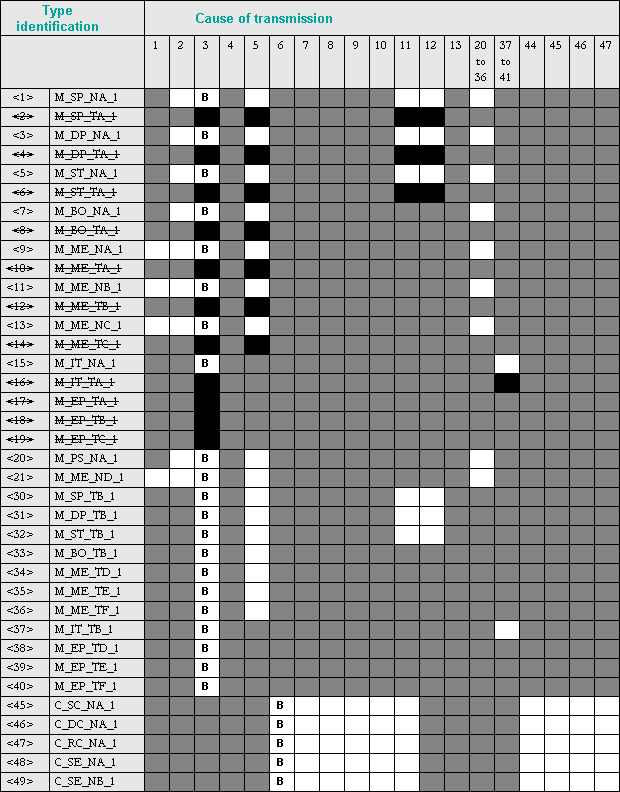
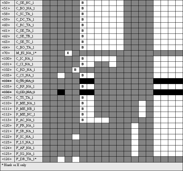
Type identifier and cause of transmission assignments
(station-specific parameters)
Shaded box = combination of type identification and cause of transmission not provided in the application-specific standard.
Black box: combination of type identification and cause of transmission not allowed in the application-specific standard.
Blank box = combination of type identification and cause of transmission not used.
Combinations of type identifier and cause of transmission:
'X' if only used in standard direction
'R' if used in reverse direction
'B' if used in both directions
Basic application functions
Station initialization
(station-specific parameter; "X" if used)
|
|
Remote initialization |
Cyclic data transmission
(station-specific parameter; "X" if used in standard direction or "R"
if used in reverse direction or "B" if used in both directions).
|
|
Cyclic data transmission |
Read procedure
(station-specific parameter; "X" if used in standard direction or "R"
if used in reverse direction or "B" if used in both directions).
|
|
Read procedure |
Spontaneous transmission
(station-specific parameter; "X" if used in standard direction or "R"
if used in reverse direction or "B" if used in both directions).
|
|
Spontaneous transmission |
Double transmission of information objects with cause of transmission spontaneous
(station-specific parameter; specifies "X" for information objects, triggered by a single state change, that are transmitted both with the type identification without time information and with the appropriate type identification with time information)
The following type identifications may be transmitted in succession caused by a single status change of an information object. The particular information object addresses for which double transmission is enabled are defined in a project-specific list.
|
|
Single-point information M_SP_NA_1, M_SP_TA_1, M_SP_TB_1 and M_PS_NA_1 |
|
|
Double-point information M_DP_NA_1, M_DP_TA_1 and M_DP_TB_1 |
|
|
Step position information M_ST_NA_1, M_ST_TA_1 and M_ST_TB_1 |
|
|
Bitstring of 32 bits M_BO_NA_1, M_BO_TA_1 and M_BO_TB_1 (if defined for a specific project) |
|
|
Measured value, normalized value M_ME_NA_1, M_ME_TA_1, M_ME_ND_1 and M_ME_TD_1 |
|
|
Measured value, scaled value M_ME_NB_1, M_ME_TB_1 and M_ME_TE_1 |
|
|
Measured value, short floating point value M_ME_NC_1, M_ME_TC_1 and M_ME_TF_1 |
Station interrogation
(station-specific parameter; "X" if used in standard direction or "R" if used in reverse direction or "B" if used in both directions)
|
Global |
||
| Group
1 |
Group
7 |
Group
13 |
| Group
2 |
Group
8 |
Group
14 |
| Group
3 |
Group
9 |
Group
15 |
| Group
4 |
Group
10 |
Group
16 |
| Group
5 |
Group
11 |
The information object addresses per group must be specified in a separate table . |
| Group
6 |
Group
12 |
Clock synchronization
(station-specific parameter; "X" if used in standard direction or "R" if used in reverse direction or "B" if used in both directions)
|
|
Clock synchronization |
optional
Command transmission
(object-specific parameter; "X" if used in standard direction or "R"
if used in reverse direction or "B" if used in both directions)
|
|
Direct command transmission |
|
|
Direct setpoint command transmission |
|
|
Select and execute command |
|
|
Select and execute setpoint command |
|
|
C_SE ACTTERM used |
|
|
No additional definition |
|
|
Short pulse duration (duration determined by system parameter in the outstation.) |
|
|
Long pulse duration (duration determined by system parameter in the outstation.) |
|
|
Persistent output |
|
|
Supervision of maximum delay in command direction of commands and setpoint commands |

|
Maximum allowable delay of commands and setpoint commands |
Transmission of integrated totals
(object-specific parameter; "X" if used in standard direction
or "R" if used in reverse direction or "B" if used in both directions
).
|
|
Mode A: Local freeze with spontaneous transmission |
|
|
Mode B: Local freeze with counter interrogation |
|
|
Mode C : Freeze and transmit by counter-interrogation commands |
| Mode D: Freeze by counter-interrogation command, frozen values reported simultaneously | |
|
|
Counter read |
|
|
Counter freeze without reset |
|
|
Counter freeze with reset |
|
|
Counter reset |
|
|
General request counter |
|
|
Request counter group 1 |
|
|
Request counter group 2 |
|
|
Request counter group 3 |
|
|
Request counter group 4 |
Parameter loading
(object-specific parameter; "X" if used in standard direction or "R"
if used in reverse direction or "B" if used in both directions).
|
|
Threshold value |
|
|
Smoothing factor |
|
|
Low limit for transmission of measured values |
|
|
High limit for transmission of measured values |
Parameter activation
(object-specific parameter; "X" if used in standard direction or "R"
if used in reverse direction or "B" if used in both directions).
|
|
Activation/deactivation of persistent cyclic or periodic transmission of the addressed object |
Test procedure
(station-specific parameter; "X" if used in standard direction or "R"
if used in reverse direction or "B" if used in both directions)
|
|
Test procedure |
File transfer
(system-specific parameter; specifies the function used with "X")
File transfer in monitor direction
|
|
Transparent file |
|
|
Transmission of disturbance data of protection equipment |
|
|
Transmission of sequences of events |
|
|
Transmission of sequences of recorded analog values |
File transfer in control direction
|
|
Transparent file |
Background scan
(station-specific parameter; "X" if used in standard direction or "R"
if used in reverse direction or "B" if used in both directions)
|
|
Background scan |
Acquisition of transmission delay
(station-specific parameter; "X" if used in standard direction or "R"
if used in reverse direction or "B" if used in both directions)
|
|
Acquisition of transmission delay |
Definition of time outs
| Parameter | Default value | Remarks | Selected value |
| t0 | 30s | Timeout of connection establishment | |
| t1 | 15s | Timeout of send or test APDUs | |
| t2 | 10s | Timeout for acknowledgements in case of no data messages t2<t1 | |
| t3 | 20s | Timeout for sending test frames in case of a long idle state, t3>t1 |
Maximum range of values for all time outs: 1 to 255 s, accuracy 1 s
Maximum number of outstanding I-format APDUs k and latest acknowledge w
| Parameter | Default value | Remarks | Selected value |
| k | 12 APDUs | Maximum difference receive sequence number to send state variable | |
| w | 8 APDUs | Latest acknowledge after receiving w I format APDUs |
Maximum range of values k: 1 to 32767 (215 - 1) APDUs, accuracy 1 APDU
Maximum range of values k: 1 to 32767 APDUs, accuracy 1 APDU (Recommendation: w should not exceed 2/3 of k)
Portnumber
| Parameter | Default value | Remarks |
| Portnumber | 2404 | In all cases |
RFC 2200 suite
RFC 2200 is an official Internet Standard which describes the state of standardization of protocols used in the Internet as determined by the Internet Architecture Board (IAB). It offers a broad spectrum of actual standards used in the Internet. The suitable selection of documents from RFC 2200 defined in this standard for given projects has to be chosen by the user of this standard.
|
|
Ethernet 802.3 |
|
|
Serial X.21 interface |
|
|
Other selection(s) from RFC 2200 |
List of valid documents from RFC 2200
1. ....................................................................
2. ....................................................................
3. ....................................................................
4. ....................................................................
5. ............................................... .....................
6. ....................................................................
7. etc.