
Panel for connections - IEC 60870 104
Open the panel for configuring IEC driver connections via the System management panel, Driver IEC tab:
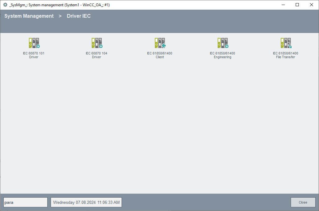
Click on the IEC 60870 104 Driver button to open the following panel. The panel allows you to create the datapoints for your connections (e.g. Gateway1 and Gateway2) and all addresses of the associated remote control components.
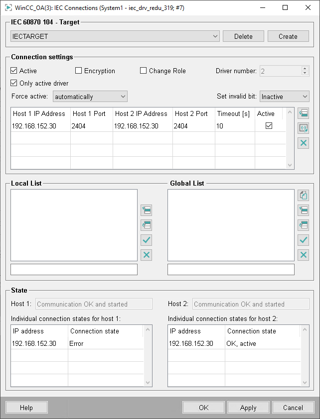
IEC 60870 104 - Target
Configuration of the connection datapoints
Select here the datapoint name (connection name) you want to configure from the combo box.
Click on Create to create a new datapoint of the _IecConnection datapoint type. (including a redundant DP). Valid characters for a connection datapoint are [a-z,A-Z,0-9,_]. In a redundant WinCC OA project a datapoint with the name "<datapointName>_2" is created automatically.
Click on Delete to delete the selected DP.
Click on Apply to apply the creation/deletion.
Connection settings
Allows the configuration of separate "physical" connections. Here you can see all configured connections for this driver datapoint.
Active
Sets all configured connections to (in)active.
Only active driver
Only the active driver of a redundant project connects to the server.
Ignore Timestamps
When active the incoming timestamps are ignored.
Encryption
Enables TLS encryption for the IEC driver (see also IEC 104 - encrypted connection).
Change Role
Activates change of IEC 104 driver communication role to TCP server. Normally the TCP server is the controlling station and TCP client is the controlled station.
Force active
You can configure the behavior of the redundant connections via the combo box: either the driver should select a connection automatically or an explicit connection can be selected. In the latter mode, a connection switch-over does not take place even if the connection gets lost. Therefore, all connections are listed in the combo box (that are displayed in the table) and can be selected.
Invalid Bit
Configures the invalid bit setting on connection loss. See IEC driver internal DP _IecConnection.Config.SetInvalidBit.
Table
In the table you can find all configured connections. The columns display the connection parameters. In the last column you can set the connection active/passive.
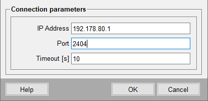
Click on the ![]() button to specify the connection parameters for a new connection.
button to specify the connection parameters for a new connection.
Click on the ![]() button to change the parameters of the selected connection.
button to change the parameters of the selected connection.
Click on the ![]() button to delete the selected connection from the table.
button to delete the selected connection from the table.
In case of the IEC 104 several connections can be configured. Specify the following parameters : IP Address, Port and Timeout.
The timeout is used to establish a connection meaning that new connection requests are made in this interval.
10 seconds is the recommended value.
In the redundant state the panel differs only by the table and the connection status. In a redundant state, the host and the redundant host as well as the both ports are displayed.
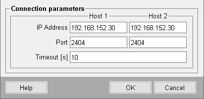
The timeout is the same for both hosts. You can also set the redundant/non-redundant connection to active/passive. Thus, also here only one check box is available. At the bottom the both connection states of the corresponding connections are displayed.
Local List
Enter the addresses of the stations that can only be accessed via this connection (see IEC driver, basics). The addresses are specified in the text box below the lists. Format: " region.component.module.value.subaddress" (= Common Address.Information Object Address, see also Panel for defining the peripheral addresses of the IEC driver). A value of "*" means "all values between 0 and 255".
The buttons allow you to insert, edit or delete (see Default buttons).
Global List
Enter the addresses of all stations that are not only accessible via this station
(IECTARGET1) but rather via other stations, too. This saves you having to enter
parameters several times for redundant connections. In our example the same stations
are also accessed via IECTARGET2. So if you set the parameters for IECTARGET2
connections, click ![]() to open a panel and copy the global lists from IECTARGET1 to the
current datapoint IECTARGET2.
to open a panel and copy the global lists from IECTARGET1 to the
current datapoint IECTARGET2.
Status
Displays the (DP global) communication states (States.ConnState):
-
0: Communication error
-
1: Communication OK and started
-
2: Communication OK but not yet started
-
3: Connection deactivated
-
> 4: Connection state undefined