Data Mapping
This chapter provides information and instructions to configure the data mapping of a WinCC OA SECS Gateway.
CNS views define the structure which is used by the gateway manager to map data from PLC datapoints to SECS-specific features. How the host can access the data is described in the section Data Access.
Data Types
The following table shows which WinCC OA datatypes are mapped to which SECS datatypes.
| WinCC OA types | SECS types | WinCC OA types | SECS types |
|---|---|---|---|
| BLOB_VAR | A | UINTEGER_VAR | U4 |
| BIT64_VAR | U8 | FLOAT_VAR | F8 |
| BIT32_VAR | U4 | TEXT_VAR | A |
| CHAR_VAR | A | DYN_*_VAR | Vector of according "*" type |
| BIT_VAR | BL | LONG_VAR | I8 |
| INTEGER_VAR | I4 | ULONG_VAR | U8 |
Vectors are not defined in detail in SEMI E5, but they are used in several E5 messages and
represented as a single object which holds a value list of a SECS type. For example, a U4
vector (DYN_UINTEGER_VAR) looks like this: [12,23,25]. It is important to
note that a vector is not a list, because a vector is not a fully defined data type in SEMI E5
section 9.
Messages which are sent and received manually through the HostInterface DPs can be implemented with all available SECS data types.
CNS Structure
A CNS-view represents a SECS Gateway manager. The CNS-trees represent the SECS equipment.
The node ID of the tree must be equal to the internal DP of the _SecsEquipment DPT (without the underscore). The following CNS structure can be expanded to the needs of the project. For example, adding equipment constants or events which are not defined yet.
The CNS structure is read by the gateway at startup and after changes to the CNS view and its child nodes, so that a restart of the manager is not necessary for the changes to take effect.
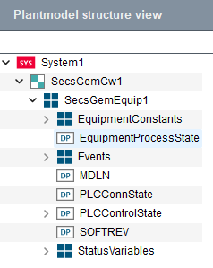
Each SECS tree (equipment connection) consists of the following child nodes to configure the fundamental GEM requirements. All nodes need to be linked to a DPE, except the events:
| Node ID | Node type | DPE-Type | Description |
|---|---|---|---|
| PLCConnState | DP | Int, uint | This node needs to hold the connection state DPE of the PLC which should be represented as SECS equipment. |
| PLCConnState_2 | DP | Int, uint | Only needed in a redundant system. This node needs to hold the _2 connection state DPE of the PLC which should be represented as SECS. |
| PLCControlState | DP/Structure | Int, uint | This node needs to hold the control state DPE of the PLC or of the mock which should be represented as SECS equipment. |
| MDLN | DP | String | This node should hold a DPE which defines the MDLN (model number) of the equipment (see SEMI E30 and E5 for more details). |
| SOFTREV | DP | String | This node should hold a DPE which defines the SOFTREV (software revision) of the equipment (see SEMI E30 and E5 for more details). |
| Events | Structure | - | This node holds events assigned to the equipment. See section Events for a detailed description. |
| EquipmentConstants | Structure | - | This node holds the equipment constants of the equipment. |
| StatusVariables | Structure | - | This node holds the status variables of the equipment which must be defined by the user. |
| EquipmentProcessState | DP | Int, uint | This node should hold a DPE which represents the equipment process state. Note that the Process State must be implemented on the PLC or in a CTRL-Script. |
EquipmentConstants
Each SECS equipment needs equipment constants for configuration purposes. The pre-defined
constants in this section must be configured to fulfill the functionality of the fundamental
GEM requirements. The Node IDs of equipment constants need the prefix ECID_
which stands for Equipment Constants ID. Additional equipment constants can be added but
their use case must be implemented on the application side and are not automatically
considered in the gateway manager. For the host only gathering their data and changing their
values is supported via the corresponding messages.
| Node ID | EC Name | Node type | DPE-Type | Description |
|---|---|---|---|---|
| ECID_100 | AnnotateEventReportsEnabled | DP | Uint, int, bool | This node should contain a DPE that defines whether or not the equipment sends annotated event reports. True: Event reports are sent with S6F13. False or no DPE linked: Event reports are sent with S6F11. |
| ECID_101 | EstablishCommunicationsTimeout | DP | Uint, int | This node should hold a DPE which configures the establish communications timeout (see SEMI E30 Section 6.4.2.1 for further specification). |
| ECID_102 | TimeFormat | DP | Uint | This node should hold a DPE which configures the time format used for SECS messages (see SEMI E5 section 9.10 table 7 "Variable Dictionary" "TimeFormat"). |
Events
Event notification is a fundamental GEM requirement and therefore mandatory for the SECS Gateway. The configuration via CNS is described in this section. For further details on the event notification and event reports see SEMI E5 S6F11/13 message and to SEMI E30 section 7.3.1.2
Each SECS equipment needs an events structure node. Events can be added dynamically in the CNS structure. They are automatically considered by the gateway manager, if trigger DPs are linked. The structure of the node IDs for events and all underlying child nodes is defined in the following table:
| Node ID | Parent node | Node type | DPE-Type | Description |
|---|---|---|---|---|
| CEID_<CEID> | Events | Structure | - | This node holds the event name and ID. |
| (Trigger DPEs) | CEID_<CEID> | DP | - | All DP nodes with the CEID_<CEID> as parent are considered as trigger
DPEs. On each value change of one of the configured trigger DPEs an event is sent to
the host. If this trigger DPE node has the CNS property OA:SECS,
the event will only be sent if the current value equals one of the property values.
A detailed description of this CNS property can be found in section OA:SECS. |
| RPTID_<RPTID> | CEID_<CEID> | Structure | Any datatype from Data Types | This node holds the report name and ID. Multiple report nodes can be associated with a CEID_<CEID>. |
| (Report DPEs - with annotation: VID_<Unsigned ID> when AnnotateEventReportsEnabled is True, otherwise no specific id) | RPTID_<RPTID> | DP | Any datatype from Data Types | All nodes with the RPTID_<RPTID> as parent are considered as report DPEs. These DPEs configure which data is handed to the host when an event gets triggered. DP nodes represent a value and structure nodes represent the start of a list element with underlying DP nodes or nested lists. |
Event and Report configuration
A CEID such as CEID_4000 can be used for an event named
ControlOnline-Offline. Trigger DPEs can be configured as child nodes
below CEID_4000 and can optionally define matching values via the OA:SECS
property.
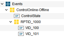
The report structure can be configured below a report node such as RPTID_1000. Report DPEs define the values transferred to the host when the event is triggered. For annotated event reports, report values can use VID_<Unsigned ID> node ids.
Events and reports can also be created via CTRL-Scripts and the SECS Gateway library
function secsgw_createEventOrReport (in secsGateway.ctl)
Mandatory Events
Events are in general not mandatory, but the following events for the control state must be configured to get the correct information from the host about the equipment's control state:
- ControlOnline-Offline
- ControlLocal
- ControlRemote
When creating CNS gateway or equipment structures via the corresponding buttons, these events get automatically created.
PLCControlState
The control state is an essential SECS equipment feature which is required for the operation of the equipment and host message exchange. Therefore, it is mandatory to configure the corresponding CNS nodes. For further information on the control state model, refer to the SEMI E30 standard, section 6.5.
The PLCControlState CNS node has child nodes which hold configuration (Config) and command (Command) DP nodes. The child nodes are described in the following table:
| Node ID | Node type | DPE-Type | Description |
|---|---|---|---|
| Config | Structure | - | Structure node. Child nodes are config nodes for the control state. |
| Config.OAOperateControlStateAllowed | DP | uint, int, bool | This node should hold a DPE which describes if operating or configuring the control state is allowed within WinCC OA or if these configurations and operations are only allowed inside the PLC. True: PLCControlState can be operated in WinCC OA. PLCControlState configurations can be changed in WinCC OA. False: Only the PLC can control the PLCControlState and the control state configurations. |
| Config.StartingControlState | DP | uint, int | This node should hold a DPE where the starting control state is defined. |
| Config.DefaultOfflineControlState | DP | uint, int | This node should hold a DPE where the default offline control state is defined (see SEMI E30 section 6.5.4). |
| Command | Structure | - | Structure node. Child nodes are command nodes for operating the ControlState on the PLC. |
| Command.LocalRemote | DP | uint, int, bool | This node should hold a DPE with the information and command possibility to go into online-local (false) or online-remote (true) control state. |
| Command.HostAckGoOnline | DP | uint, int, bool | This node should hold a DPE which is triggered after the PLCControlState changes to the "Attempt-Online" state, a S1F1 is sent to the host and if the host answers with S1F2. |
| Command.HostRejGoOnline | DP | uint, int, bool | This node should hold a DPE which is triggered after the PLCControlState changes to the "Attempt-Online" state, S1F1 is sent to the host and if the host answers with S1F0 or the transaction timeout is reached. |
| Command.HostReqOnline | DP | uint, int, bool | This node should hold a DPE which is triggered if the host sends a S1F17 (GoOnline) request. |
| Command.HostReqOffline | DP | uint, int, bool | This node should hold a DPE which is triggered if the host sends a S1F15 (GoOffline) request. |
| Command.EquipReqOnline | DP | uint, int, bool | This node should hold a DPE which is triggered if the operator in WinCC OA wants the equipment to go into Online ControlState. |
| Command.EquipReqOffline | DP | uint, int, bool | This node should hold a DPE which is triggered if the operator in WinCC OA wants the equipment to go into Offline ControlState. |
OA:SECS
To fully configure the SECS Gateway, the CNS-property OA:SECS is used for
specifying event trigger values on event trigger DP nodes or for defining the "Connected"
state on the PLCConnState node of an equipment. The property must be defined as a JSON array
containing numbers. The CNS panels in the plantmodel editor's SECS section already take
care of that, but if a CTRL-script is used the property can be set and queried via the
functions cnsSetProperty and cnsGetProperty.
Example for setting the OA:SECS property:
main()
{
  dyn_int diSecsValues = makeDynInt(1, 2, 3);
  string sSecsValuesEncoded = jsonEncode(diSecsValues);
  cnsSetProperty("System1.View1:Node3.Node1", "OA:SECS", sSecsValuesEncoded);
}
Example for reading the OA:SECS property:
main()
{
  string sJsonValues;
  cnsGetProperty("System1.View1:Node3.Node1", "OA:SECS", sJsonValues);
  dyn_int diSecsValues = jsonDecode(sJsonValues);
  DebugTN(diSecsValues); // dyn_int [1, 2, 3]
}
CNS Configuration
For the SECS Gateway, a specific structure in the CNS is required. The structure can be automatically created for existing _SecsGateway and _SecsEquipment DPs in the SECS section of the plant model editor.
System
The system node in the plant model editor's SECS section looks like the following:
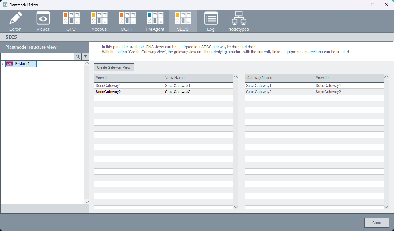
The assignment between view and gateway is done via drag and drop from the left table to the according gateway DP in the right table. Furthermore, a view for a specific and already existing gateway can be created by clicking the Create Gateway View button. After clicking the button, you can select one of the already existing SECS Gateway DPs for which the CNS structure should be created. If equipment connections were already linked in the gateway configuration panel, then the underlying equipment structure for the CNS configuration is also automatically created and only needs to be configured in the plantmodel editor.
View
The view node in the plantmodel editor's SECS section looks like the following:
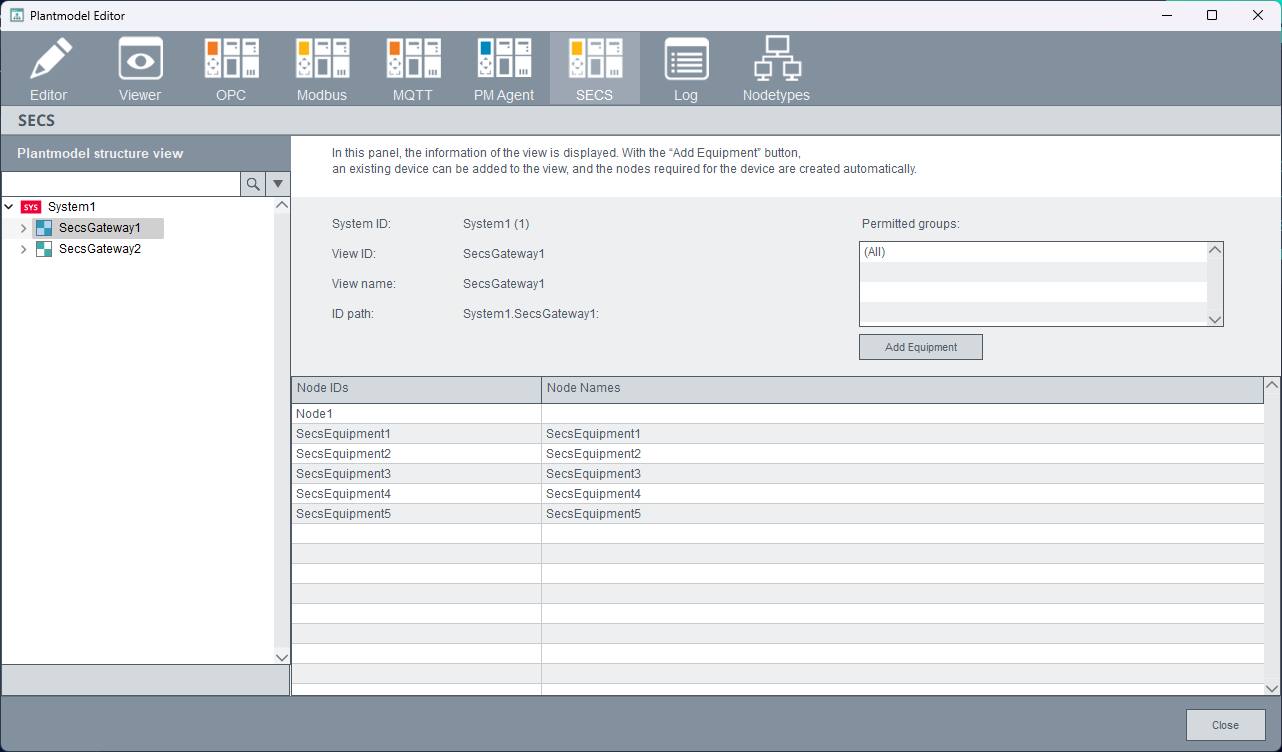
With the Add Equipment button, the CNS structure for an equipment connection is created automatically for an existing and selected _SecsEquipment DP. For example, when a new equipment connection is added to an already existing gateway and CNS structure, this button automates the process of adding all the nodes in the plantmodel editor.
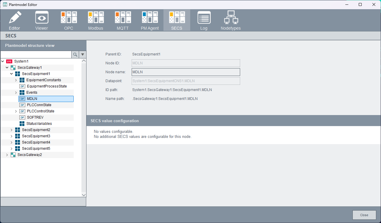
Node
Nodes in the plant model editor's SECS section have three different panels, depending on the node ID.
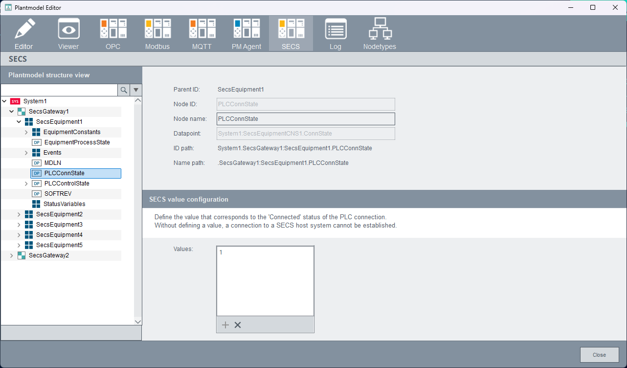
Event Trigger DPs and PLCConnState nodes
These two node types can set SECS-specific values in the plantmodel editor's SECS section as CNS property. The property's name is OA:SECS.
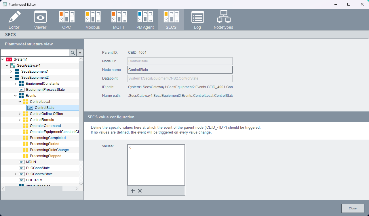
For event trigger DPs the property values are used to define specific trigger values of the linked DP. When values are defined in the list, the event only gets triggered when the DP value is equal to one of the defined values. If no values are defined, the event triggers on every value change of the linked DP.
For the PLCConnState node, a SECS value configuration is needed as well. A value can be defined in this node, representing the value of the "Connected" state of a PLC, whose data is used within the equipment connection.
All other nodes
All other nodes in the SECS section do not have the option to specify additional values via the panel and instead show the following panel: