
Defining the Peripheral Address
This chapter describes the definition of peripheral addresses for the SECS driver.
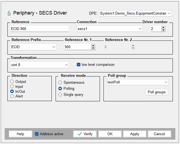
Click on the "_address" config of a DPE, select the driver type SECS and click on Configure... to open the following panel.
Reference
Address reference definition depends on the type of data which is gathered or sent. The driver supports direct collection of alarms, events and traces via a specific address reference scheme. Also, status variables and device constants have a separate address reference to read/write them onto specified DPEs. In addition to that, every E5-Message can be sent/received via Input or Output address references. When using full E5 messages as JSON-strings to request and/or respond, the addresses of Input and Output configs must be the same reference string to map the request/response to each other. The address schemes are described in the following tables.
Arbitrary E5-Message - Direction Host to Device
When the host sends any arbitrary request to the device, an address reference as described in the following table must be used.
| Address-reference scheme | Example | Transformation | Description |
|---|---|---|---|
| HREQ.<number> | HREQ.231 | string | The host sends a request via JSON-string to the device. The number in the reference can be chosen arbitrarily. |
Arbitrary E5-Message - Direction Device to Host
Any request from the device to the host has a reserved address reference which needs to be used to gather the request and respond to it.
| Address-reference scheme | Example | Transformation | Description |
|---|---|---|---|
| EREQ.<x>.<y> | EREQ.7.3 | string | x and y are the numbers corresponding to the E5 stream (x) and function (y). This example receives the stream 7 with function 3. This address reference scheme is used to map any arbitrary request from the equipment to the host. The host must answer this request with the corresponding E5 response message. |
Status Variables and Device Constants
Status Variables - by the definition in the SEMI E5 Standard - are read-only so they can only be used with the “Input” address direction. Device Constants - by the definition in the SEMI E5 Standard are read/write so they can be used with “Input”, “Output” or “In/Out” address direction. For reading the variable/constant value, spontaneous input, polling or single query can be used.
| Address-reference scheme | Example | Transformation | Description |
|---|---|---|---|
| SVID.<SVID> | SVID.250 | all | DPEs with this address reference get set by the driver after a S1F3R request which contains the SVID (Status Variable Identifier) from the address reference. From the response (S1F4) the status variable values are written to the _original_value of the DPEs with corresponding address references. |
| ECID.<ECID> | ECID.220 | all | DPEs with this address reference get set by the driver after a S2F13R request which contains the ECID (Equipment Constant Identifier) from the address reference. From the response (S2F14) the equipment constant values are written to the _original_value of the DPE with corresponding address references. When setting the _original_value of DPEs with this address reference and direction “In/Out” or “Output” via dpSet or in the para, the driver creates and sends a S2F15R request to change the value on the equipment. |
Event, Alarm, Trace
Alarms, Events and Traces sent by the equipment: The address-reference must be according to the E5 message type you want to receive on the configured DPE and need direction “Input”.
| Address-reference scheme | Example | Transformation | Description |
|---|---|---|---|
| CEID.<CEID> | CEID.4001 | string | S6F11 and S6F13 are automatically written to a DPE with an address-reference like this. The <CEID> must match the according collection event ID that should be captured on this DPE. |
| ALID.<ALID> | ALID.1001 | string | S5F1 is automatically written to a DPE with an address-reference like this. The <ALID> must match the according alarm ID that should be captured on this DPE. |
| TRID.<TRID> | TRID.6000 | string | S6F1 is automatically written to a DPE with an address-reference like this. The <TRID> must match the according trace ID that should be captured on this DPE. |
Alarm
To map alarms from the equipment in WinCC OA different DPEs can be used, and two different alarm address-references are implemented.
| DPE-Type | Address-reference scheme | Example | Description |
|---|---|---|---|
| String | ALID.<ALID> | ALID.1000 | S5F1, S5F6 and S5F8 are automatically written to a string DPE with an address-reference like this. The <ALID> must match the according alarm ID and the JSON string of the S5F1 message should be captured on this DPE. |
| Uint, Integer, Float, Bool | ALID_A.<ALID> | ALID_A.1000 | S5F1, S5F6 and S5F8 is automatically written to a uint, int, float or bool DPE with an address-reference like this to map equipment alarms to WinCC OA alarms. The <ALID> must match the according alarm ID that should be captured on this alarm. The direction should be set to “Alert”. |
Connection
Holds the name of the connection.
Driver number
Defines the number to which driver this address belongs to.
Reference Prefix
The reference prefix describes the type of address reference that is configured. Via this combo box, the address type can be changed in the reference string. The following prefixes are available:
- HREQ
- EREQ
- CEID
- TRID
- ALID
- ALID_A
- ECID
- SVID
Reference Nr. 1
The use of the first reference number depends on the configured reference prefix. The following table describes the usage:
| Prefix | Usage |
|---|---|
| HREQ | User defined ID to match the request output address to the response input address |
| EREQ | Equipment request E5 stream number. The function number can be configured via the “Reference Nr. 2” |
| CEID | Collection Event ID of the equipment event |
| TRID | Trace ID of an defined equipment trace |
| ALID | Alarm ID of an equipment alarm |
| ALID_A | Alarm ID of an equipment alarm |
| ECID | Equipment Constant ID |
| SVID | Status Variable ID |
Reference Nr. 2
The second reference number is only available for the “EREQ” reference prefix. Here it is used to describe the function number of the equipment request which should be received on the DPE.
Transformation
The following transformations are available:
- string
- binary
- bool
- int 64
- int 32
- int 16
- int 8
- uint 64
- uint 32
- uint 16
- uint 8
- float 64
- float 32
DPEs for receiving and/or sending full E5 messages must use “string”. Receiving status variable values and receiving/sending equipment constant values must use the corresponding data type as transformation. The DPE where the address is defined must match the transformation data type. For receiving multi-instance alerts, the transformation is disabled.
Direction
- Output
- Use when sending a E5 message or Equipment Constant value to the equipment
- Input
- Use when receiving E5 message, Alarm, Event, Trace, Status Variable value or Equipment Constant value from equipment
- In/Out
- Use when sending or receiving Equipment Constant values
- Alert
- Use on uint, int, float or bool DPE to map SECS-II alarm to WinCC OA alarms
Receive mode
Specifies how input values should be received:
- Unsolicited
- Use when receiving values or E5 messages spontaneously.
- Polling
- Specify a poll group which polls the required value in the specified time interval.
- Single query
- Values gets queried when a single query is triggered.
Low level comparison
Specifies if an old/new comparison should be made before the value gets written to the _original.._value .