
Defining the peripheral addresses of the S7 driver
This chapter describes the definition of symbolic addresses (only for S7-300/400 devices!) and S7 protocol addresses. Click on the address config of a datapoint element, select the driver type NATIVE SIMATIC S7 from the combo box and click on the button "Configure". The opened panel allows to configure the peripheral address for the S7 driver.
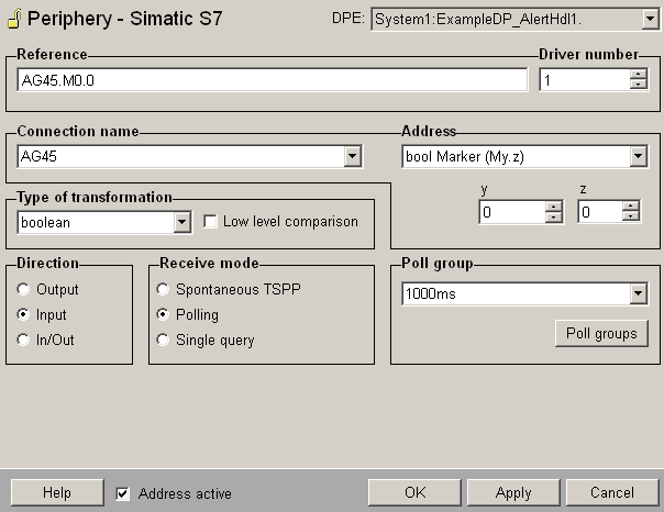
Reference
Shows the defined peripheral address. The address can be entered manually or via the components described later. The reference string consists of the connection name which is defined for a specific device and the defined address.
Syntax - S7 General
<Connection name>.<S7 specific address>Syntax - S7 Symbolic Address
<Connection name>.$<Symbolic address>Syntax - S7 SINUMERIK
<Connection name>./<SINUMERIK BTSS (BedienTerminalSchnittStelle) address>
E.g. Sinu1./Nck/State/nckAliveAndWell
The value in the reference field is automatically checked.
Driver number
Must match the number of the S7 driver assigned to the PLC.
Connection name
Select the configured connection from the combo box. The communication takes place via this connection name. The peripheral devices to which the S7 driver establishes a connection are created via the S7 configuration panel (see Configuration of the S7 driver).
Address
Define the address that is assigned to the datapoint element at the peripheral device. The following two options are available:
-
S7 protocol specific addresses: Select the necessary address via the combo box and specify the x, y or z components of the address via the inserted spin buttons. The reference string consists of the connection name and the here configured address.
-
Symbolic addresses (only for S7-300 and S7-400 devices): Select "Symbolic address" via the combo box and open the symbol editor via the inserted "..." button (see also Symbolic for S7-300/400 for further information).
Type of transformation
Choose the transformation type from the combo box. The transformation type is the interpretation of the data that was read on the peripheral device. The transformation type must match the defined address type (if e.g. 4 bytes are read from the PLC the type of the transformation has to be float or int32). If the address is defined via the combo box and spin buttons the correct transformation type is selected automatically.
If the type "default" is selected in the combo box, the driver determines the transformation type depending on the value in the Reference field. For symbolic addresses the mapping in the corresponding datapoint of type _S7_Symbolics is checked automatically.
For reading/writing a string either symbolic addresses or byte addresses from the table (see possible S7 data types) can be used. When writing a string only If transformation type "string" is used for polling an input, the number of bytes can be set. E.g. DB100.DBB10:100 polls 100 Bytes, beginning from the address DB100.DBB10. Note that you can specify the number only for the transformation type "string".
The first two Bytes of a S7 string are used for length information. Therefore, the actual length of the S7 string is the defined length (100 in the example above) minus these two bytes. For configuring a string address, proceed as follows: A Byte array with start address DB100.DBB10 is created in the PLC. Because of the length information, the address DB100.DBB12 must be configured as start byte in the reference field.
If you set the config entry useStringLengthInfo = "Y" you can define the actual address (DB100.DBB10), since the first two bytes are automatically cut.
If you click on OK or Apply it is checked if the transformation type matches the S7 address type defined in the reference field.
You can find the possible S7 data types and the type of transformation in WinCC OA in a table at the end of this page.
-
When writing a value of type TIME, note that the reference string has to point to the first target data block!
-
The transformation type "default" must not be used for symbolic addresses.
-
For S7 1200 Models the "date time long (DTL)" transformation must be used instead of the "dateTime" transformation!
Low level comparison
This option can only be chosen if the direction was set to input or in/out. If it is selected the driver only sends data if the value is changed. The comparison is based on raw data without any conversion. In a low level comparison the single bits of byte blocks are compared to old values and when a bit changes the value is updated in WinCC OA.
Direction
Defines whether the values of a datapoint element are sent in the send direction (output), in the receive direction (input) or in both directions (In/Out).
When the values of a datapoint element are sent in both directions (In/Out), then this datapoint element must not be directly subordinated to a struct node (structure of values).
Receive mode
The receive mode for the input can be Spontaneous TSPP, Polling, Single query or Polling on use. Spontaneous TSPP can only be used if S7 - TSPP has been activated in the S7 configuration panel for the corresponding connection.
Poll group
Poll groups can be created and configured via this button. Already existing poll groups can be modified, enabled or disabled via this button. Use the combo box to select a poll group.
Address active
If the Address active check box is enabled the address is created at the driver (seeReference tables). Attributes can be set and queried for an inactive address, however, the address does not exist for the driver. This means that with this datapoint element no values can be sent to or received from the PLC.
Possible WinCC OA data types
The following WinCC OA data types can be used to define peripheral addresses for the S7 driver:
-
char, uint, int, float, bool, bit32, string, time, blob, S5Time, TimeOfDay
-
dyn_char, dyn_uint, dyn_int, dyn_float, dyn_bool, dyn_bit32
Possible S7 data types
In an S7-300 or an S7-400 the following data types with the following names for the addresses are available:
| S7-200 / S7-300 / S7-400 / S7-1200 address (corresponds to the address in the PARA panel) | Type of exchange | WinCC OA transformation type |
|---|---|---|
| My.z | read / write bits | boolean |
| DBx.DBXy.z | read / write bits | boolean |
| Ey.z / Iy.z | read input bits | boolean |
| Ay.z / Qy.z | read / write output bits | boolean |
| MBy | read / write bytes | byte |
| DBx.DBBy | read / write bytes | byte |
| EBy / IBy | read input bytes | byte |
| ABy / QBy | read / write output bytes | byte |
| MWy | read / write words | int 16, uint16, S5Time, Date |
| DBx.DBWy | read / write words | int 16, uint16, S5Time, Date |
| EWy / IWy | read input words | int 16, uint16, S5Time, Date |
| AWy / QWy | read / write output words | int 16, uint16, S5Time, Date |
| MDy | read / write double words | int 32, uint32, Int32WithQuality, UInt32WithQuality, TimeOfDay |
| DBx.DBDy | read / write double words | int 32, uint32, Int32WithQuality, UInt32WithQuality,TimeOfDay |
| EDy / IDy | read input double words | int 32, uint32, Int32WithQuality, UInt32WithQuality,TimeOfDay |
| ADy / QDy | read / write output double words | int 32, uint32, Int32WithQuality, UInt32WithQuality,TimeOfDay |
| MDyF | read / write floating point | float, FloatWithQuality |
| DBx.DBDyF | read / write floating point | float, FloatWithQuality |
| Tn | read / write timers | uint 16, S5Time |
| Zn | read / write counters | uint 16 |
| MBx and DBx.DBy | transformation of date and time. |
byte, dateTime, Note:
DTL must be used for S7-1200 |
| Bx.DBW, EW, MW, AW | bitString |
| S7-1500 address (corresponds to the address in the PARA-Panel) | Type of exchange | WinCC OA transformation type |
|---|---|---|
| DBx.DBBy | read / write bytes | byte |
| DBx.DBWy | read / write words | int 16, uint16, S5Time |
| DBx.DBDy | read / write double words | int 32, uint32, Int32WithQuality, UInt32WithQuality, TimeOfDay |
| DBx.DBDyF | read / write floating point | float, FloatWithQuality |
| DBx.DBy | transformation of date and time. | byte, dateTime, |
The following dynamic types work for input TSPP data:
dyn char, dyn unsigned, dyn int, dyn float, dyn bool. If WinCC OA receives a TSPP block and a dyn DPE with an address has been configured at the beginning, or in this block, all data starting from that address is mapped to the dyn DPE. For the dyn bool, define the address with a bit number 0!
When writing a value of type TIME, note that the reference string has to point to the first target data block!
For the letters E resp. A (input resp. output) in the address variables you can also use I resp. Q.
S7 LOGO - Variable memory (VM)
In case of S7 LOGO devices, (analog) inputs, (analog) outputs and (analog) flags are stored in the variable memory (VM). In WinCC OA communication the content of the variable memory is mapped to the data block DB1.
-
Inputs (I), outputs (Q) and flags (M) can be accessed directly or via the mapped VM address in data block DB1. E.g. if you want to address the digital input I5 of a LOGO!0BA7 device, you can either define I0.4 or DB1.DBX923.4 in the address panel.
-
Direct access to analog inputs (AI), analog outputs (AQ) and analog flags (AM) is not possible. Therefore, you have to use the VM addresses. E.g. if you want to access analog flag AM1 of a LOGO!0BA7 device, you have to define DB1.DBW952 in the address panel.
The following mapping tables show the VM addresses for the respective device type (0BA7 and 0BA8).
| Block type | from VM address | to VM address | Range | WinCC OA |
|---|---|---|---|---|
| I | 1024 | 1031 | 8 Bytes | I1 = I0.0 or DB1.DBX1024.0 |
| AI | 1032 | 1062 | 32 Bytes | AI1 = DB1.DBW1032 |
| Q | 1064 | 1071 | 8 Bytes | Q1 = Q0.0 or DB1.DBX1064.0 |
| AQ | 1072 | 1102 | 32 Bytes | AQ1 = DB1.DBW1072 |
| M | 1104 | 1117 | 14 Bytes | M1 = M0.0 or DB1.DBX1024.0 |
| AM | 1118 | 1244 | 128 Bytes | AM1 = DB1.DBW1118 |
| NI | 1246 | 1261 | 16 Bytes | NI1 = DB1.DBX1246 |
| NAI | 1262 | 1388 | 128 Bytes | NAI1 = DB1.DBW1262 |
| NQ | 1390 | 1405 | 16 Bytes | NQ1 = DB1.DBX1390 |
| NAQ | 1406 | 1468 | 64 Bytes | NAQ1 = DB1.DBW1406 |
| Block type | from VM address | to VM address | Range | WinCC OA |
|---|---|---|---|---|
| I | V923.0 | V925.7 | 3 Bytes | I1 = I0.0 or DB1.DBX923.0 |
| AI | VW926 | VW940 | 16 Bytes | AI1 = DB1.DBW926 |
| Q | V942.0 | V943.7 | 2 Bytes | Q1 = Q0.0 or DB1.DBX942.0 |
| AQ | VW944 | VW946 | 4 Bytes | AQ1 = DB1.DBW944 |
| M | V948.0 | V951.2 | 4 Bytes | M1 =M0.0 or DB1.DBX948.0 |
| AM | VW952 | VW982 | 32 Bytes | AM1 = DB1.DBW952 |