
Modbus
The address space of the WinCC OA Modbus/TCP server is defined via assigned CNS views. Therefore the server address space is independent from the datapoint structure of the respective project and can be freely defined for each server (see also Modbus/TCP server for further information).
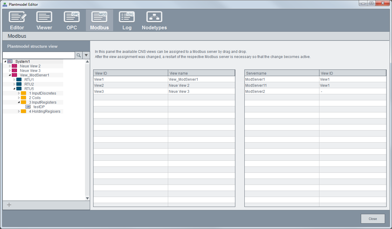
System overview
After creating a CNS view you can assign it to the appropriate WinCC OA Modbus/TCP server per drag & drop. Click on the system element of the tree to open the overview of available views and servers. Note that the respective Modbus server must be restarted after assigning a CNS view.
View
The following overview panel is displayed if you click on a view. System ID, view ID etc. are displayed as defined via the Editor tab, however, the fields are read-only.
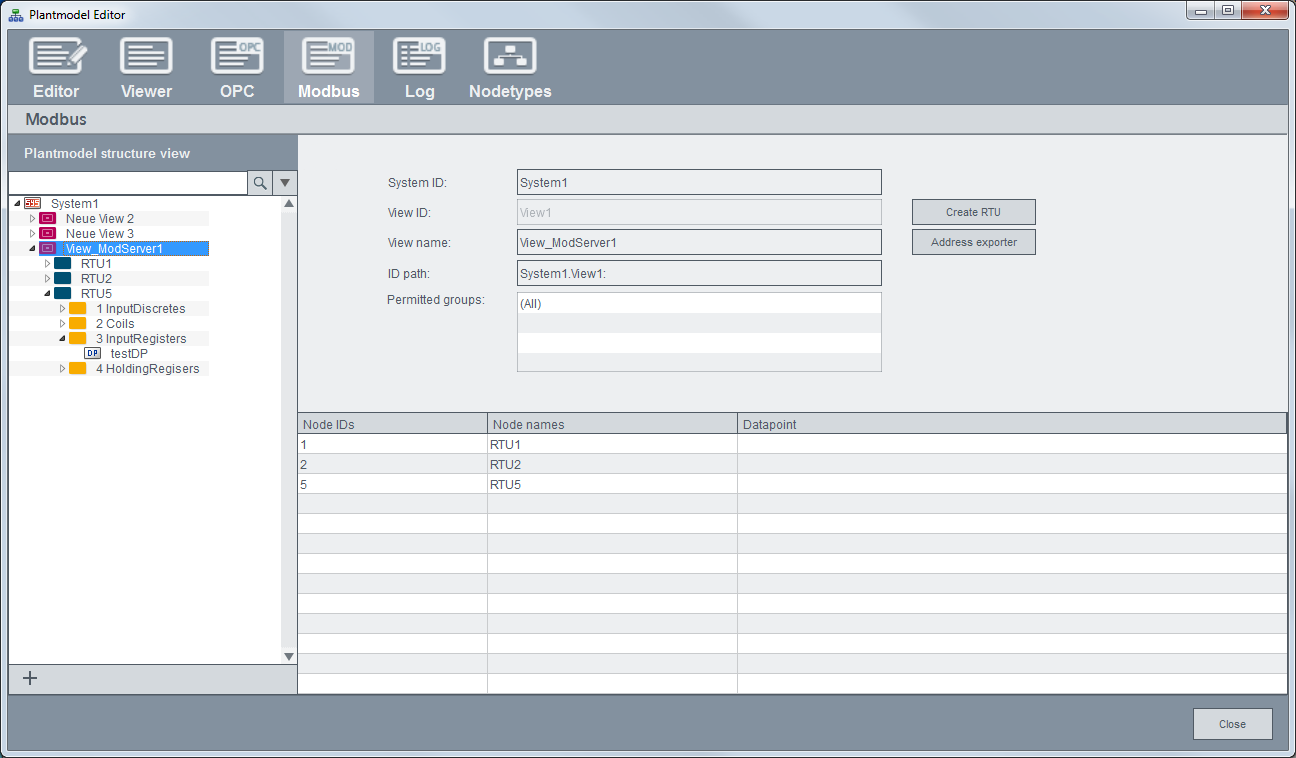
Create RTU
Automatically creates an appropriate structure for an RTU (remote terminal unit). After clicking on this button, you have to define the RTU number. The corresponding node ("RTU<number>") with its sub-elements is created. The stated RTU number is also used as node ID.
When querying data with a Modbus/TCP client, you have to define this node ID as unit address (e.g. in the client configuration panel, see also Configuration of the Modbus/TCP driver).
The created sub-elements are equivalent to the four memory areas (refer to Modbus/TCP server details) in which the data must be stored. Following four nodes are created:
-
1 InputDiscretes
-
2 Coils
-
3 InputRegisters
-
4 HoldingRegisters
Address exporter
Modbus relevant information of the CNS view is exported to a file which can be used by other programs (e.g. for the configuration of a Modbus client project).
Node
This panel shows information on the respective node (as described in Node).
The node ID in the screenshot below represents the following Modbus addres: 5 -> RTU unit address, 3 -> Input register, 1 -> Modbus register address.
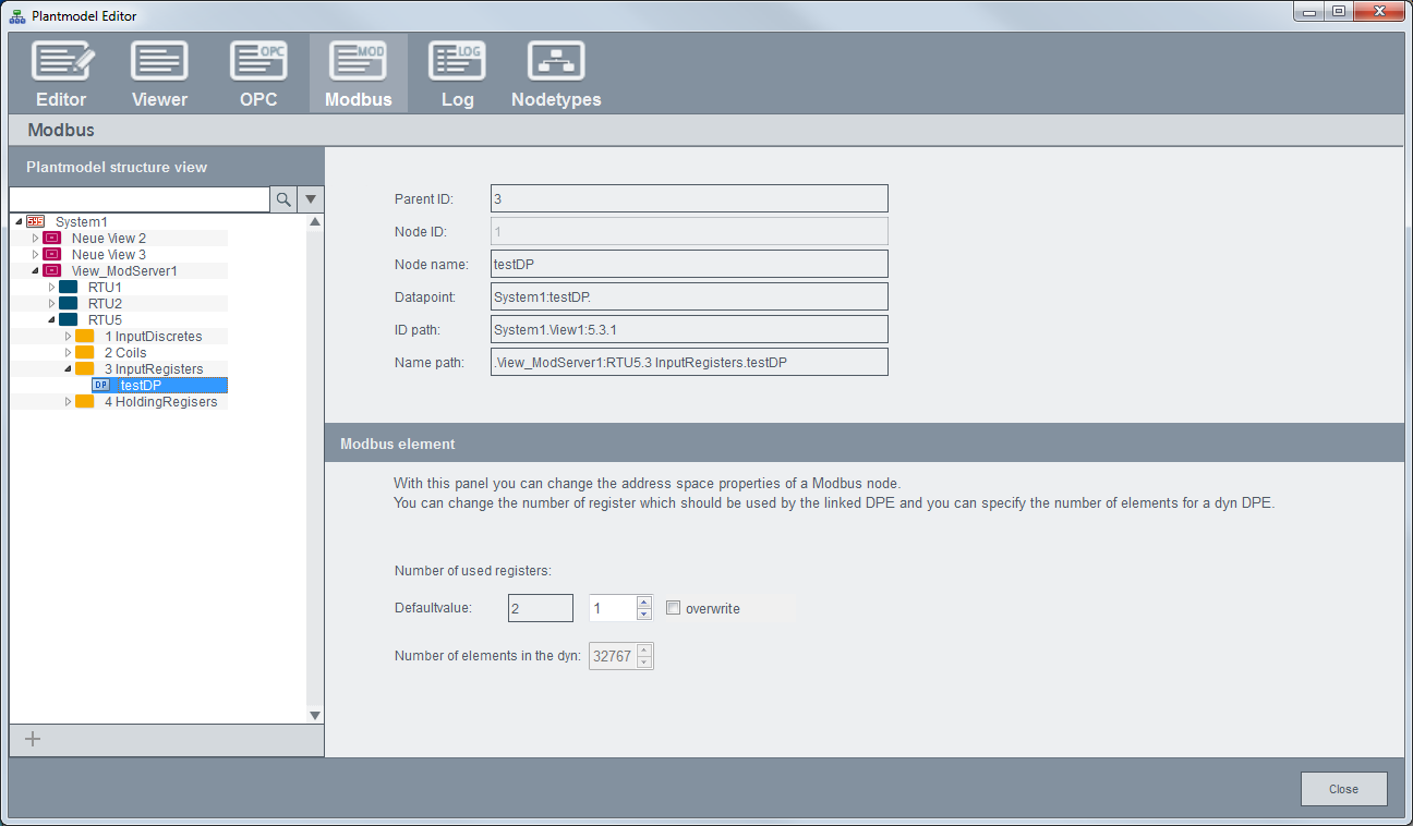
Modbus element
The specified values for the number of used registers or dyn elements are automatically written on the node's UserData with the appropriate key. You can also use the CTRL function cnsSetProperty.
-
Number of used registers: Defines how many registers shall be used for the respective element. E.g. an int type needs 2 registers per default. If you only need an int16, assign an int32 datapoint and set the number of used registers to 1.
-
Number of elements in the dyn: Defines how many dyn elements shall be mapped to the Modbus registers.
Refer to the Modbus/TCP server details chapter for further information on data types and registers.