
Defining the Peripheral Addresses of the DNP3 Driver
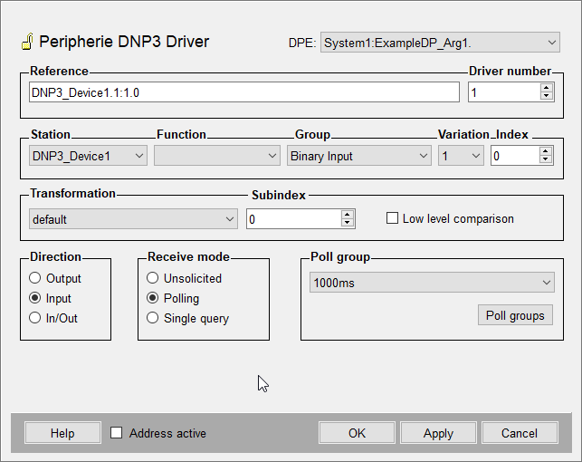
Click on the address config of a datapoint element to define the peripheral address. Select from the combo box the driver type DNP3 and click on Configure. Now, the peripheral address can be configured in the panel (see figure below).
The peripheral address (reference string) can be either entered directly to the "Reference" field or can be selected from the combo boxes and spin buttons of the particular components (station, function, group, variation, index). The reference string consists of the following fields:
<outstation>:<function>.<group>:<variation>.<index>
Driver Number
Number of the related manager that starts the DNP3 driver (e.g. -num 4).
Station
Name of the internal datapoint for the outstation. After the configuration of the DNP3 driver this is selected automatically.
Function (function code)
Optional entry. Typically, the function code is deduced from the object group entry. The specification is needed for object groups, where more than one function code is possible (see Compatibility of the DNP3 Driver).
Normally, a function code must be specified for output addresses. Following options are available:
- Write
- Select
- Operate
- Direct Operate
- Direct Operate, no Ack
- Freeze
- Freeze no Ack
- Freeze Clear
- Freeze Clear no Ack
Group
The object group. If different groups refer to the same data (e.g. Binary Input and Binary Input Event) only Binary Input can be configured, because the data of both groups is mapped to the same input address.
Specifying BinaryCommand or AnalogOutput the response state must be mapped to an input address. This is required for evaluation of the command state.
Variation
Optional entry. The variation of the object group defines the format of the DNP3 point's data. The specification is needed for data, which should be returned in a specific format (see Compatibility of the DNP3 Driver).
Normally, there is input-sided no variation specification necessary, as the data is mapped to WinCC OA datapoint elements in this format as received. Output-sided the variation in the peripheral address defines the format the data should be sent. Thus, here a specification of the variation is not needed.
Index
Specifies the index of an object in a group.
Transformation
Select the transformation type from the combo box. The transformation type is the interpretation of the data, which has been read from the peripheral device. The transformation has to compare with the address (if e.g. 4 bytes was read from the outstation, the transformation type must be float or int32). If the address has been defined by using the combo boxes and spin buttons, the right transformation type for a specific address is selected automatically.
If you select the default type from the combo box, the driver defines the transformation type automatically dependent on the value of the reference field.
Low-Level-Comparison
This option can be activated only then, when the direction is set to input or in/out (bidirectional peripheral communication). This option causes that data will be sent to the Event Manager only if they have changed. This comparison is based on raw data without conversion.
The low-level-comparison is an old/new comparison and is already executed with the data, which have been received from the outstation (in opposition to smoothing, where the data are already pointed at the datapoints).
Direction
Defines whether the values of a datapoint element are sent in the send direction (output), in the receive direction (input) or in both directions (in/out).
During the configuration it should be considered that for some groups only input and for other only output can be selected.
Receive Mode
The receive mode for the receive direction can be set to unsolicited, polling or single query.
Poll Group
Select an already existing poll group. If no poll group is available, it has to be created in a separate panel with specific polling parameters. The panel can be opened by clicking the button Poll groups (see also Poll Groups for more information about poll groups and poll parameters).
Address active
If the Address active check box is checked, the driver address will be used (see Reference Tables). An inactive address is possible and the attributes can be set and queried, but will not be used by the driver. That means, that no values can be sent at the outstation or can be received from the outstation.
Configuration of special DNP3 groups
Binary Commands
DNP3 Binary Commands (group 12, variation 1) or "Control Relay Output Block" (CROB) are complex objects with a lot of different information. The mapping of this information in the peripheral address takes place via subindices. To transmit a command you have to write the appropriate value as described in the table on the respective datapoint.
The DNP3 standard defines the following fields:
| Field | WinCC OA Subindex | Description | DPE Type | Direction |
| OpType | 0 |
Defines together with TCC the type of the operation: 0: NUL 1: PULSE_ON 2: PULSE_OFF 3: LATCH_ON 4: LATCH_OFF |
uint | Output |
| QU | 1 | Queue Field | bit | Output |
| CR | 2 | Clear Field | bit | Output |
| TCC | 3 |
Trip-Close Code Field 0: NUL 1: CLOSE 2: TRIP 3: RESERVED |
uint | Output |
| Count | 4 | This is the number of times the outstation shall execute the operation. | uint | Output |
| On-Time | 5 | This is the duration, expressed as the number of milliseconds, that the output drive remains active. | uint | Output |
| Off-time | 6 | This is the duration, expressed as the number of milliseconds that the output drive remains non-active. | uint | Output |
| StatusCode | 7 | This field is output-sided always fix-defined with 0. Input-sided it returns the error state of the command. | uint | Output |
For detailed information on CROBs see DNP3 specification.