Assign Symbols to DPT
A direct link between the symbol and its corresponding datapoint type forms the foundation for the simplified design of user interfaces using Simple Symbols. This connection is established through a configuration panel and is later utilized as a Simple Symbol.
Configuration
To establish a connection between symbol and datapoint type, open the Assign Symbol to DPT panel, located under the menu point Simple Symbols.
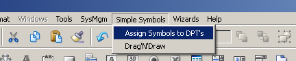
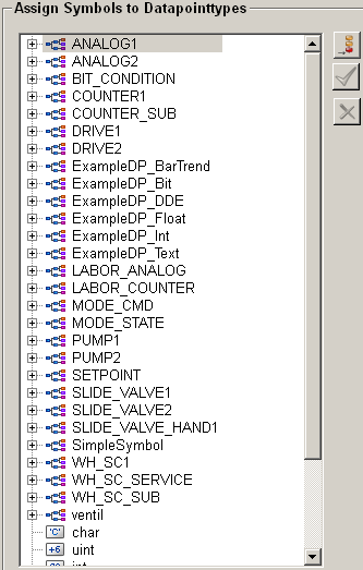
The menu point opens the overview panel for all existing datapoint types and general data types which are available in the WinCC OA project.
Following general data types are available for the Simple Symbols: char, uint, int, float, bool, bit32, string, time
Datapoint types
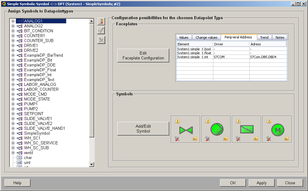
The datapoint type overview allows you to select the datapoint type that should be connected with a symbol.
Changes within the assignments between the elements of the datapoint type and the $-parameters are only displayed correctly after the symbol panels are reopened.
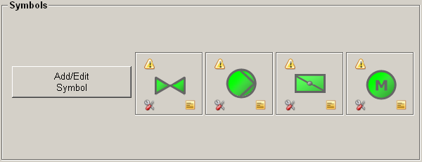
Insert new symbol 
Save configuration 
Saves all changes that have been made to the datapoint type.
Save changes before selecting a new datapoint type, or else all changes for the data point type will be lost.
Delete symbol configuration 
Removes the symbol, that has been selected inside the datapoint type overview.
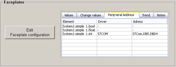
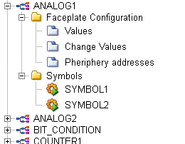
Faceplate configuration
The faceplate configuration allows you to adapt the faceplate to your needs. You can open the configuration panel using the Edit faceplate configuration button. The available configurations are described in the following sections:
Main Faceplate
The main faceplate represents the panel that opens when you click the symbol in the user interface. The faceplate displays general information about the datapoint, which is shown within the default tabs described below.

Default
Uses a default main faceplate.
Custom
This option enables the selection of a custom main face plate.
File Selection 
Opens a selection dialog for the panel that will be used as the main faceplate. This panel will appear when you click the symbol in the user interface.
New Faceplate 
Creates a new faceplate and opens it in GEDI for editing.
A default faceplate is used, located at objects/SimpleSymbols/<DPT>/faceplates/main.xml. You can modify this file to match your design or information requirements.
Standard Tabs
The standard tabs are a set of predefined tabs that display information about the datapoint assigned to the symbol. The following tabs are available:
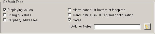
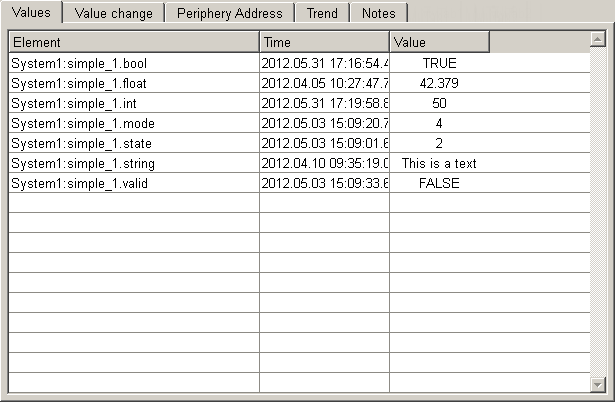
Tab for displaying values
Displays the values of the datapoint elements.
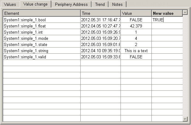
Tab for changing values
Allows you to make changes to the values within the faceplate. If the tab is activated, it is displayed within the faceplate; otherwise it remains hidden.
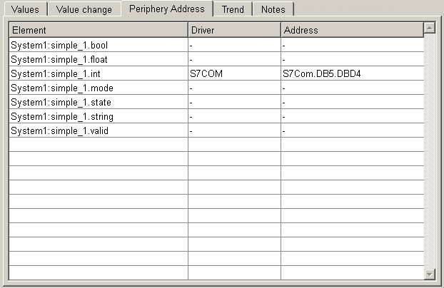
Tab for displaying periphery addresses
Displays the configured periphery addresses of the datapoint.
Alarm banner at bottom of faceplate
Activates the alert banner for the faceplate. This will be displayed under the selected tabs and allows you to display and acknowledge alerts.

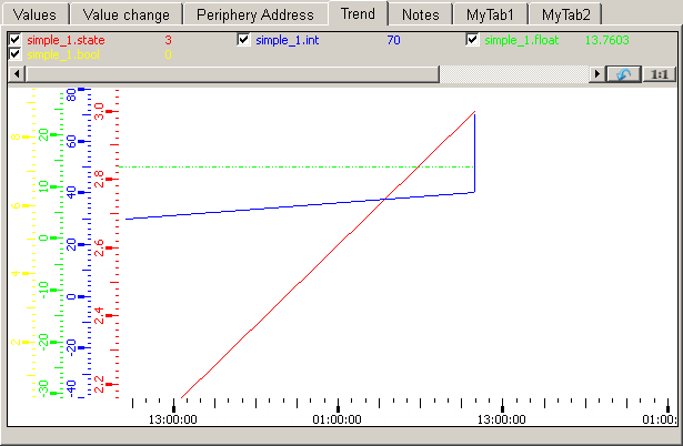
Tab with trend as defined in DPTs trend configuration
Displays the trend of the datapoint. This must be configured in the trend configuration of the datapoint type.
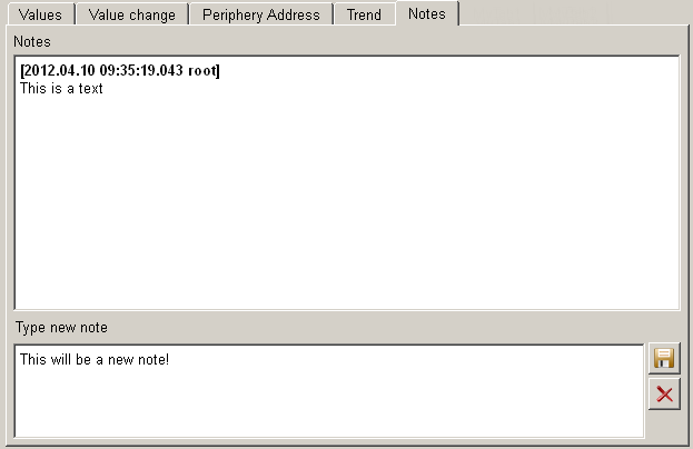
Tab for writing notes
Enables the display of notes. The note must be saved in a datapoint element. You can
select the element via the selection dialog.  .
.
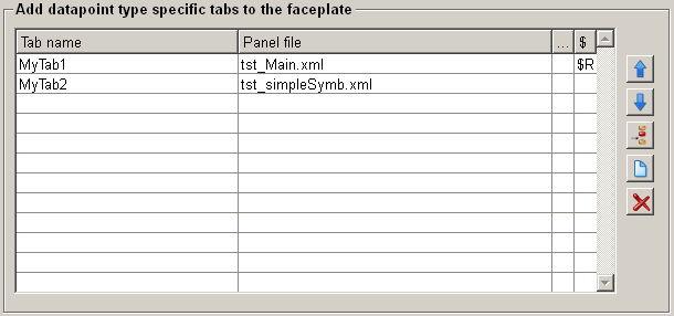
Datapoint specific tabs
You can define new tabs to display information that is not available in the default tabs (see above). To use custom tabs, you must enter the name and select the panel that should display the required information. The tab will be added to the selected default tabs and displayed within the faceplate. Double-clicking on the ... area of the row opens a selection dialog for the panel file. By double-clicking on the $ area, you can apply values to the $ parameters of the panel file.
The user-defined tabs are appended to the existing tabs within the faceplate.
The data type of the tab name is a langString, which allows you to use multiple names for different languages.
Move selected element one line up/down 

Allows you to change the order of the custom tabs. The selected entry will be moved.
Insert a new line to the table 
Inserts a new line to the table to add a new tab (name + panel).
Add new faceplate to the table and edit it in GEDI
Adds a new faceplate and opens it inside the GEDI to further customize the panel.
Remove faceplate from the table 
Allows you to remove the selected element.
A default faceplate is used. This is located under objects/SimpleSymbols/<DPT>/faceplates/user_<No>.xml and can be changed depending on the desired design or the required information.
Assigning the values
After selecting the necessary tabs and pressing the Save
configuration button (), the corresponding structure for the datapoint type
will be created, and it is now possible to assign values of the datapoint type to
the parameters of the symbol. Additionally, the displayed values for the
corresponding tabs can be selected.
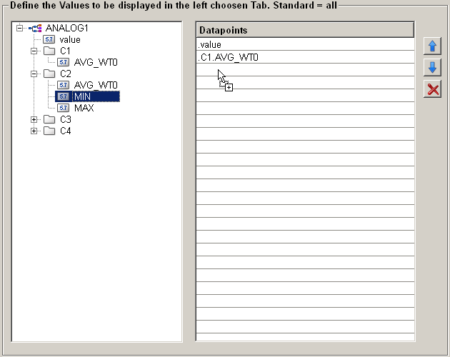
Assign the values to be displayed within a tab
You can assign the elements Values, Change Values, and Peripheryaddresses to be displayed in the corresponding tabs of the faceplate. To do this, select these elements with a mouse click in the datapoint type overview, then use drag and drop to add the desired datapoint elements to the table.
If no values are assigned (i.e., the table is empty), all values of the datapoint will be displayed by default.
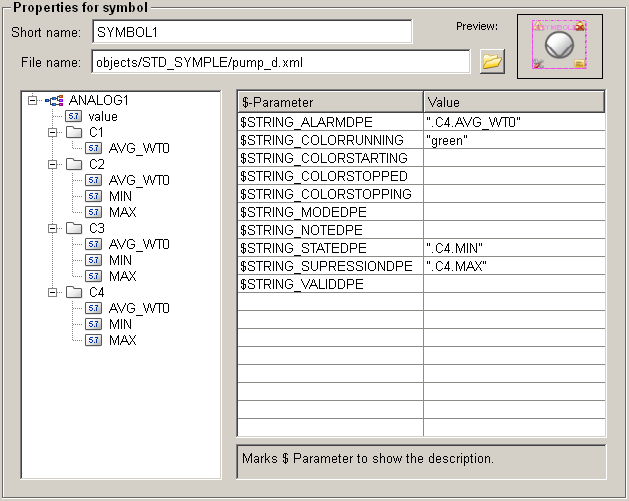
Configure symbol parameters
The configuration panel for symbols displays all available $-Parameters of the symbol. You can assign these parameters with datapoint elements or static values, such as colors. To assign a datapoint element, simply drag and drop the desired element into the value table.
This centralized configuration makes it easy to update assignments when changes are made to the datapoint type. As a result, all related panels in the user interface will automatically reflect the new assignments.
The parameters $DP, $DPE, and $Symbol-File cannot be assigned.
The $-parameter $Symbol-File is used by the ScriptWizard and must not be changed manually. This parameter serves as a link to the symbol panel.
The $-parameters $DP and $DPE are reserved for later assignment (see Drag'N Draw and are not available for configuration.
Short name
Specifies the name of the panel. This name is used to select the panel within the Drag'N Draw feature.
File Name
The file name indicates the path to the panel where the symbol is stored. You can select and add it using a selection dialog. Alternatively, you can enter the file name manually.
Only .xml panels can be used.
Description field
In the description field (located below the list of the
$-parameter), the description for the $-parameter
will be shown, if it is available.
Folder structure
When configuring a Simple Symbol, 3 folders will be created for the configured data point type. They are located under <WinCC_OA_Proj>/objects/SimpleSymbols/<DPT>/ and are used as container for the different elements of the Simple Symbol.
Following folders will be created:
- symbol/ => Contains the wrapper panel for the Simple Symbols of the datapoint type
- faceplates/ => Contains the main faceplate and the datapoint specific tabs for the Simple Symbols
The folders will only be created if a corresponding faceplate, tab or wrapper panel for the folder exists.
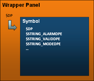
Wrapper panel
The wrapper panel is an important element of the Simple Symbols. It is used as a container for the actual symbol and the click frame (only if the symbol has been created using the ScriptWizard). The speciality is that the wrapper panel by itself only provides the $DP. The parameter will be forwarded to the symbol, which contains all necessary $-parameters. They are set when the symbol parameters are configured. The $-Parameter $DP and $DPE of the panel are assigned when the symbol is added to a panel using the Drag'N Drop functionality.