
Creating a Device Symbol (Reference)
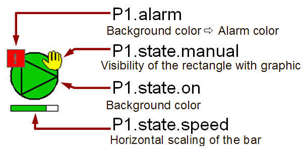
In all created dynamic objects so far, specific graphic attributes were combined with explicitly specified datapoint elements (for example background color is dependent on the element P1.state.speed). If you need several similar devices like, for example, P1, P2, P3, ... it would be wise to merge the associated graphic objects to a group, copy it several times and to position them.
Afterwards you would need to enter the right datapoint identifier for all parts that refer to adatapoint element. In case of 50 or more similar devices this can be hard (also when no changes would be necessary later).
However, you can also solve this problem much easier: in WinCC OA you can create device displays including all info panels, dialogs etc. as reusable objects. To create such a reference symbol is as easy as the so far learnt steps.

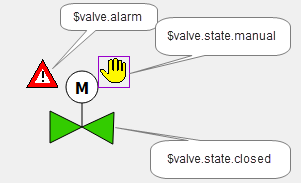
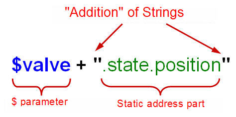
Everywhere an absolute datapoint identifier was used, it's not necessary to specify which device instance should be used. Instead of the datapoint name, enter a placeholder, the so-called $ parameter.
If the placeholder is restricted to the first part of the address, meaning the device name, you can enter the whole backmost part completely like always. You only have to specify which device is concerned, if such a reference is added to a specific position in the panel.
You will replace the placeholder ($ parameter) with the datapoint name when initializing the panel at runtime. Then all dynamic properties will be combined with the device instances specified when creating the process image.
Several advantages over the copy option result from this methodology.
-
You have to draw only one symbol display per device type.
-
When adding a device, in ideal case you only have to add a single parameter - typically a datapoint name of the device (for example V2).
-
The device symbol builds an encapsulated unit within the process image.
-
You have to change the symbol display only once in the reference file - all device instances in the different process images will be changed automatically (inheritance).
-
You can use the same methodology also for dialogs for the device symbol (for example operation panel, faceplate). The inheritance is also valid here.
Reference panels are technically normal panels. They are created in the same way like normal process and overview panels. If a reference is added to a process image, it is only composed of the drawn parts - the panel background is left out.
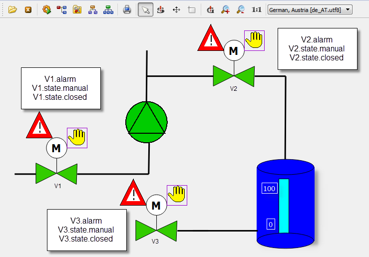
You can now create that kind of reference panel for the valve display (V1, V2 and V3) and for its input dialogs.
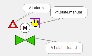
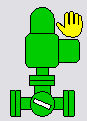
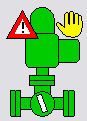
The above figure shows a technical presentation of a valve that fits to the earlier created pump symbol. You could create these easily using a polygon, a circle, a line and a polygon or a text for the character "M". The hand view is, like for the pump, a rectangle that displays a graphic. The alarm display "Reference-in-Reference" will be described first later in the chapter "Definition of an alarm handling for a datapoint".
Furthermore, WinCC OA provides ready images that can be embedded in the process view. You can create optically appealing visualizations without investing much time. In order to illustrate also this possibility, the device symbol for the valve will be created using an alternative option.
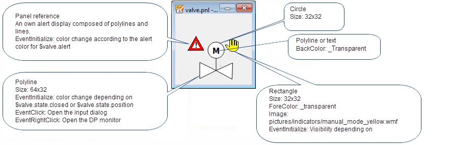
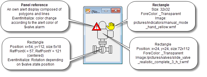
The following figure shows the associated elements that are used to build a device symbol
-
Create a new panel with a width of approximately 120x160 pixels.
-
Save this panel in your project directory under
.../panels/objects/GS_VALVE_ref.pnl.The location in the ../objects/ directory is essential for the use as reference. -
Draw a rectangle with the size 72x112 and position x = 24, y = 24.
-
Select the rectangle and open the file selection dialog for graphics through Filling > Pattern > Load of the properties window. Switch to the version directory using the combo box (for example, C:/Siemens/Automation/WinCC_OA/<version>/pictures) and select the file type "All Files (*.*)".
-
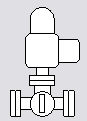
Select the file
.../pictures/valves/slide_valve_realistic_complete_3_h_t.wmf. -
Draw in the valve symbol on top right a rectangle with the size 32x32 pixels and fill it with the graphic file
.../pictures/indicators/manual_mode_hand_yellow.wmffrom the version directory.
The alarm indicator for the valve will be added first in the chapter Definition of an alarm handling for the datapoint. The indicator will be added to the reference through alarms. The symbolized flap that will rotate depending on the current opening level will be added later in this chapter (see also the next to last figure on this page).
Therefore, only a dynamic color change must be configured for the added, external graphic file. In this example a ready graphic file will be used in order to save time. The problem is that the coloration of this figure was defined in a drawing or CAD program and is not available offhand for the WinCC OA process variables.
In WinCC OA it is possible to replaceanarbitrary color for graphics of type Windows-Meta-File (*.vmf) and Enhanced-Meta-File (*.emf) dynamically at runtime. Thereby, the graphic will not be taken apart (to base objects) but remains autonomous. A converter function changes the color when it is displayed. You can access this color change through control script as well as using the wizards (simple configuration).
To enable the color change, the runtime system must know what colors of the colors the external graphic is based on, should be replaced. All parts of this graphic that were drawn in the specified color can be addressed in the same way as the background color of a WinCC OA graphic object.
-
Select the rectangle with the symbol display of the valve (slide valve).
-
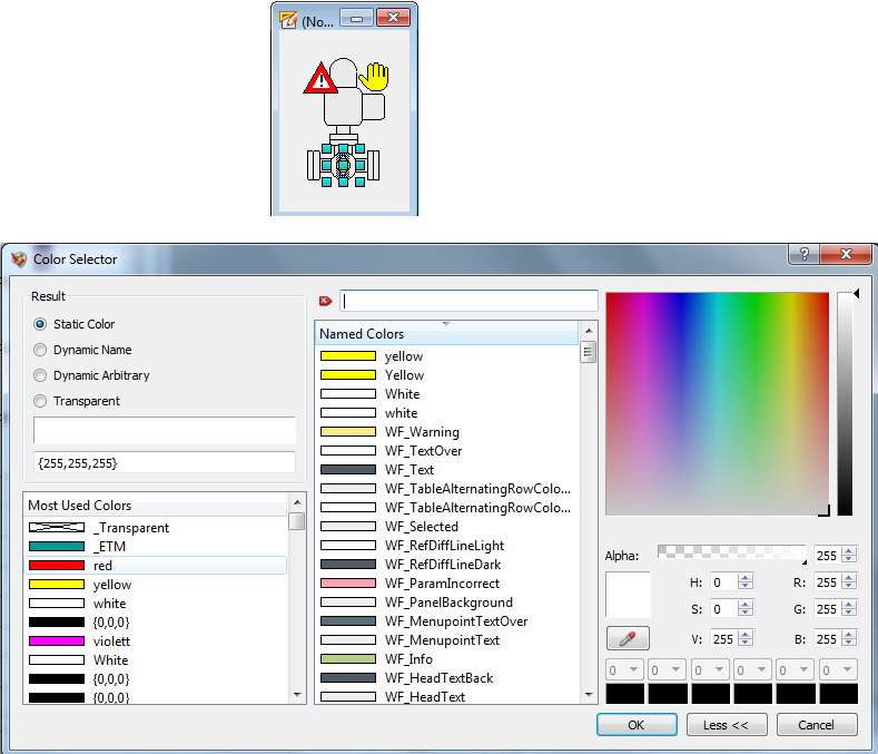
Click on the background color in the property sheet so that the color selector will be opened.
-
In the color selector click on the Color selection button (see step 3 in the figure above). The mouse pointer is now in the selection mode.
-
Thereafter, click on the color in the graphic that should be replaced later. All parts with exact this color will later be replaced.
-
Confirm your selection through OK in the color selector.
The color can be set this way only for WMF and EMF files. It can only be used if the graphic system works with true colors during the configuration as well as when displaying later at runtime. Blinking colors are not permitted for external graphic files.
Realistic process views through ready device graphics or infrastructure elements in 3D design are helpful for some users and support the recognitioneffect of the plant components. Note, however, that the basic rule is: the bigger and more complex a plant is and the more information must be displayed per process image, the simpler the symbols should be. In case of big amounts of information, you have to provide the user an abstract view that can be comprehended quickly. Note also that complex graphic objects might increase the CPU and memory load when used for a huge number of objects. For visualizations of comprehensive electric activity networks, the switching mechanisms will be, for example, displayed using a rectangle and a line.
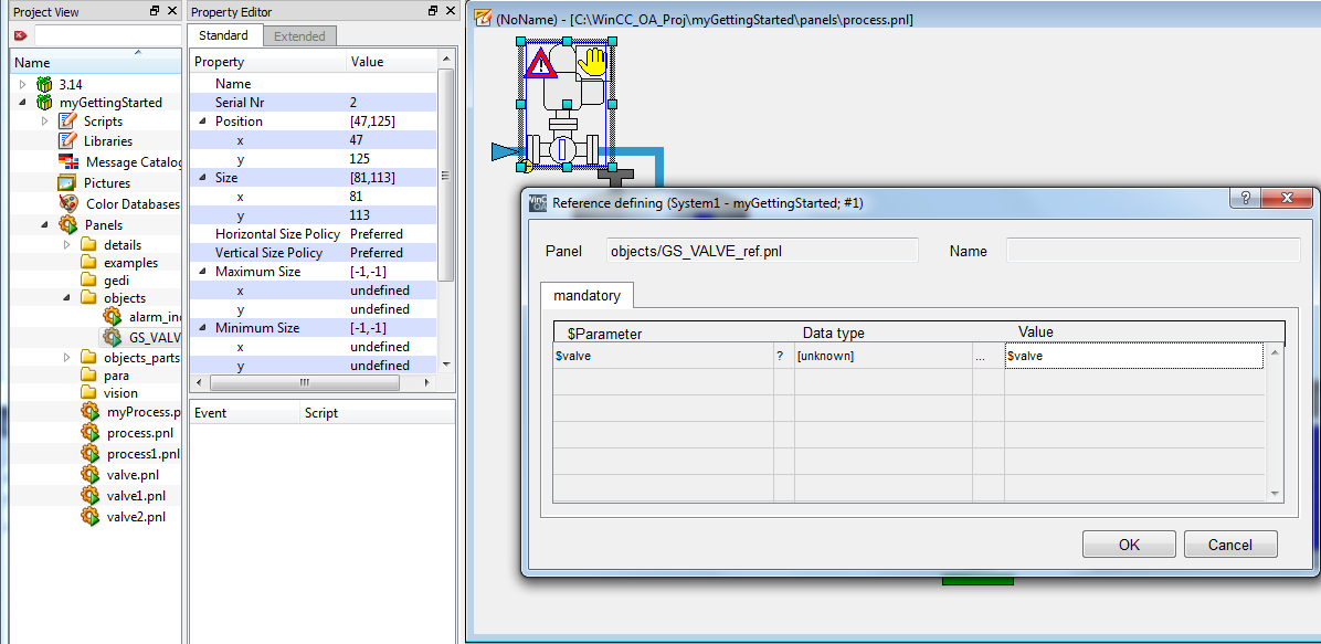
The dynamic properties are specified exactly in the same way as in the previous chapters. Merely the syntax with $ parameters will be used when specifying the datapoint element to that a graphic property should refer.
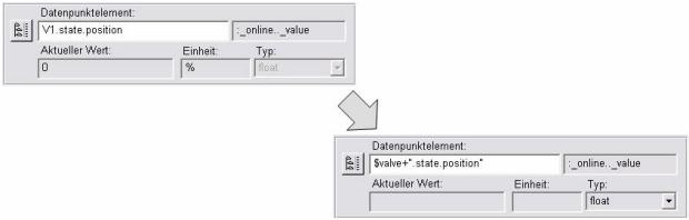
Since the wizards executes a consistency check directly after entering the element name and a datapoint element $valve+".state.position" does not exist in the system, you have to enter the data type (for example float) manually. The exact structure of the identifier for the desired datapoint element is:
The dynamic background color (filling of the valve graphic) will therefore be configured almost identical to the previous chapters.
-
Select the rectangle with the valve graphic and open the wizard for the simple configuration in the property sheet for "initialize".
-
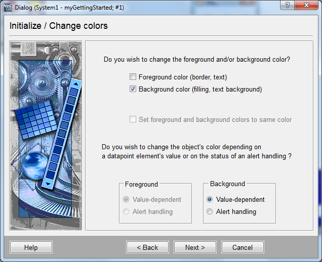
Select "Change color" for the type of animation.
-
In the next step activate the check box for "background color" (only this can be changed for the added WMF graphics) and enter "value dependent". Confirm this step withNext >.
-
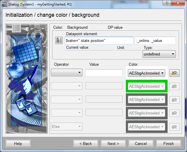
Enter the string "$valve+".state.position" for the datapoint name.
-
Select the type "float" for the data type (this is necessary since no valid datapoint with this name exists and the system can, therefore, not determine the data type itself.
-
Configure the desired colors according to the following figures.
Proceed in the same way to change the visibility for the rectangle with the yellow hand symbol depending on the datapoint element $valve + ".state.manual". Save the reference panel.
The created reference panel can now be used. In order to add it to the process image, proceed as follows:
-
Open the catalog view of the reference objects of the project directory. Therefore, select View > Catalogs >C:/WinCC_OA_Proj/myGettingStarted or the project name and location you have chosen.
-
Open the earlier created main image
process.pnl. -
Drag the reference object "GS_VALVE_ref" from the catalog to the drawing area of the panel
process.pnl. -
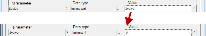
Enter the name of the first valve, for example "V1", for the "$valve" parameter (you could also choose this through click on the column with the DPE selector symbol
 in the tree view) in
the automatic displayed configuration dialog.
in the tree view) in
the automatic displayed configuration dialog. -
Confirm the configuration dialog with OK.
-
Position the valve symbol at the desired position on the drawing area.
-
Save the panel
process.pnl.
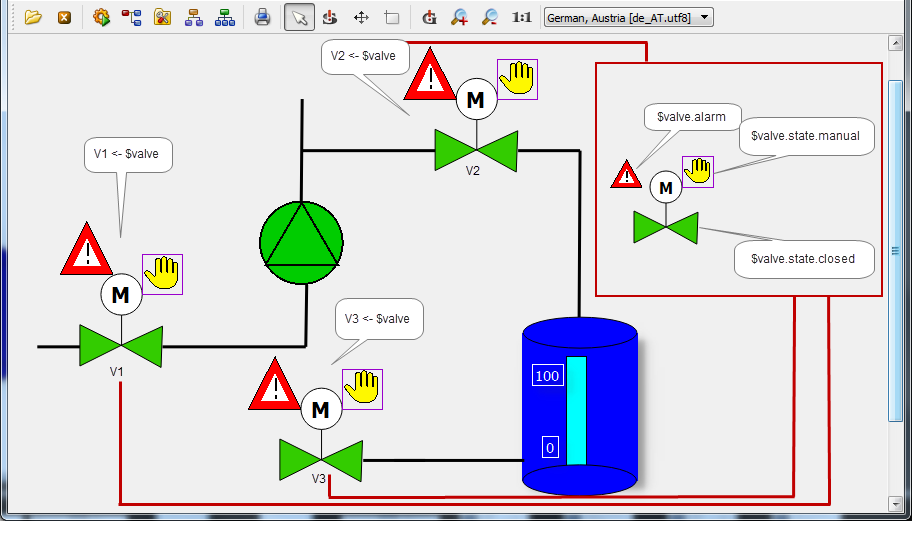
You can now view the valve V1 that was added as a reference in the preview of GEDI. Proceed in the same way for the valves V2 and V3.
When creating adatapoint identifier using a $ parameter and a static part (see figure on this page), you assigned the point "." to the static address part after the datapoint name. Consider that when selecting the datapoint name (first level) by using the datapoint selector, the point in the replacement table of the $ parameter must be deleted.
In order to arrange the selection from the catalog more clearly, you can assign a
graphic to the reference object. You can add the graphic as existing file (format *.ico,
*.bmp) or create it yourself using a small bitmap editor. For the created valve
reference object, a graphic exists in the version directory. Select the reference from
the catalog window [rightMouseClick] and select "Change Icon" option. The graphic
program will be opened. Select the image "valve_3D_grey.gif" from the version directory
through File -> Open. Save the opened image in your project
MyGettingStarted\images\objects\GS_VALVE_ref.pnl\GS_VALVE_ref.png.
![]()
The catalog view displays all *.pnl files in the directory .../panels/objects/ of the currently selected project level. You can also create sub directories for a better structure. The catalog then shows the content of these directories in own categories. Contents of further sub directories will not be shown. Thus, further sub directories are not necessary for the catalog view.
References can also be used without $ parameters. In this way, you can create static images that are needed again and again, as objects and therefore utilize the advantages of inheritance.
Reference panels are not mandatory restricted to an individual datapoint type (for example GS_VALVE). As long as the interface of $ parameters remains the same and the graphic display corresponds to the new use, reference objects can be created for universal use. A simple value display for arbitrary datapoint elements (bool, int, uint, float) of an arbitrary datapoint type can be a reference, as well as a whole pumping station.
Reference objects can be structured almost arbitrarily hierarchically (cascading). A reference object can be composed of other references as well as of normal graphic objects. Later you will insert the alarm display as (Sub)Reference into the valve symbol this way.
If you would like to view a further animation possibility more precisely, you can configure the rotation of the close mechanism depending on the current opening level of the valves. Draw therefore a small rectangle above the valve graphic and position it as indicated in the next figure. Ideally, select the position and size settings for the valve graphic as well as for the additional rectangle exactly like shown here. You can also skip this to save time and continue in the next chapter Input Dialog for Reference.
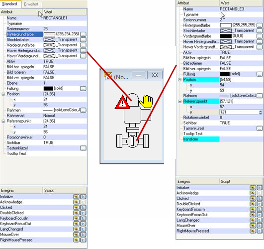
Since the desired animation type is a rotation, you have to notify the center of rotation. Each WinCC OA graphic object has the so called reference point. The properties in the property sheet are called RefPointX and RefPointY.
For the application, you have to set the center of rotation into the center of the close mechanism (rectangle). You can detect it with the coordinates of the outer boundaries (Top, Bottom, Left, Right) in the property sheet.
RefPointX = rounded up[ (Left + Right)/2 ] = rounded up[ (54 + 59)/2] =
                57
RefPointY = rounded up[ (Top + Bottom)/2 ] = rounded up[ (112 + 130)/2] = 121
-
Configure the rotation point for the rectangle (which is used as closing mechanism) in the center of the graphic object (e.g. RefPointX = 57, RefPointY = 121).
-
Open the wizards for simple configuration from the property sheet for the "Initialize" event.
-
Select the animation type "Rotate object".
-
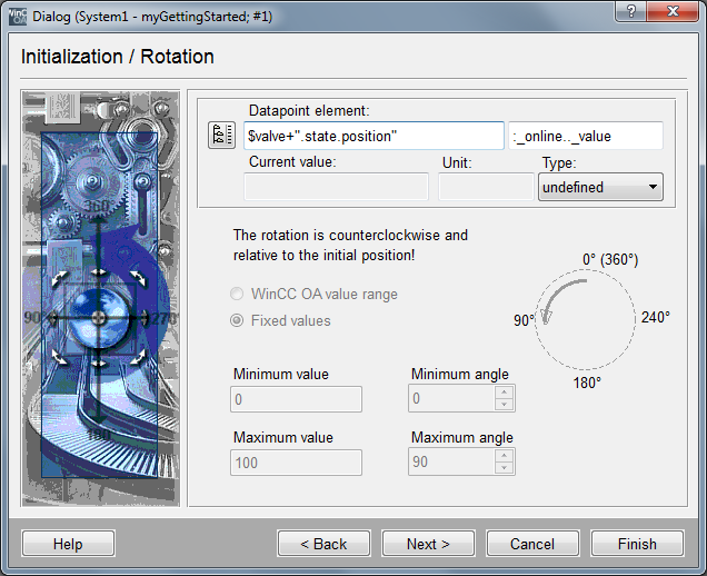
Enter the string
$valve+".state.position"in the datapoint element field. -
Select "float" for the data type in the field Type.
-
Select for the value range "Fix values" and enter the range 0...100.
-
Configure the associated rotation angle from 0° to 90° and complete the input with "Finish".
The reference point is also the basis point for a scaling (change of size) of the object. For all so far applied scalings (for example the bar for the value display), the standard reference point was, however, appropriate so that you did not need to change it.
You can also add references at runtime to a panel and also delete them per scripting. For the use of the associated CONTROL function addSymbol(), see the online help.