Time Stamp Push Protocol (TSPP) Version 2
For Time Stamp Push Protocol Version 2 the data structure required within the PLC has been reworked and streamlined which leads to performance improvements and a less complex data structures for TSPP.
TSPP Version 2 can be activated via setting the config entry [s7plus] tsppVersion:
[s7plus]
TsppVersion = 2
By default only version 1 is active to provide backwards compatibility with existing PLC configurations. A transition to version 2 requires a rework of the PLC data to the structure described below.
TSPP Data Structure
The overall TSPP buffer data structure must contain an array of unsigned 64Bit Integers followed by an EOT (End-of-Transaction) byte and a Consistency-Length Unsigned Long Integer, see example below.
Structure of 'ConsistencyLength'
The tag ConsistencyLength is subscribed to by the driver. When
anything on this tag changes, the PLC sends the entire tag to the driver, which
reads the array according to the 'length' part.
Example: 0x010203040000000A
- 4 High bytes: 0x01020304 is a random (maybe always increasing by 1) value which the driver checks again when array-data is received
- 4 Low bytes: 0x0000000A is the raw number of array entries to be read - this number is used by the driver to know how many entries of the array must be read
The Consistency bytes can be 0x00000000. If the Length is 0x00000000, nothing is read.
EOT (End-Of-Transaction) Byte
The value written to EOT contains the active session number on bits 0 and 1 and an indicator for the redundant system on bit 2.
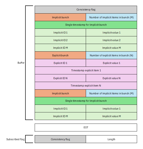
TSPP Buffer Array Structure
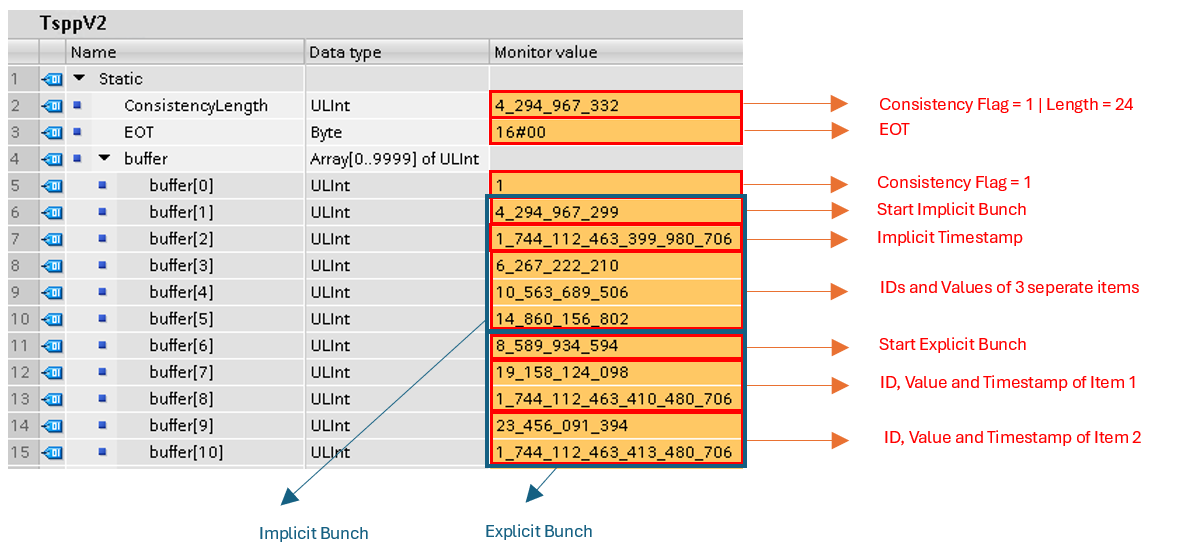
There are two types of items, that can be sent in bunches. Implicit items are defined by a single timestamp applied to all items in the bunch. Explicit items all have explicitly assigned timestamps.
Consistency
The first entry in the array is the consistency flag, which must be the same value as the consistency bytes in the ‘ConsistencyLength. (see Structure of 'ConsistencyLength')
Bunches
The data is sent in bunches. Each bunch is either defined as an implicit or an explicit bunch and holds a certain number of items. The first entry of a bunch always consists of the type of the bunch (implicit or explicit) and the number of items included.
The first entry in a bunch is structured like this:
- 4 High Bytes: either 1 to indicate an implicit bunch or 2 to indicate an explicit bunch
- 4 Low Bytes: number of items in the bunch.
-
Note:In an explicit bunch an item consists of the ID, the Value and a separate timestamp.
Implicit Bunch
Implicit Bunches consist of a single timestamp applied to all items in it. The first entry of an implicit bunch starts with the number 1 in the 4 high Bytes and the number of items in the 4 low Bytes.
Example: 0x 0000 0001 0000 0003
- The 4 high bytes
0x 0000 0001indicate that the bunch contains implicit items. - The 4 low bytes
0x 0000 0003indicate that the bunch consists of 3 items.
The second entry is the timestamp, which will be applied to all items of the bunch. The following entries hold information about the values with the dedicated IDs.
Explicit Bunch
Explicit Bunches consist of items with individual timestamps for each item. The first entry of an explicit bunch starts with the number 2 in the 4 high Bytes and the number of items in the 4 low Bytes.
Example: 0x 0000 0002 0000 0003
- The 4 high bytes
0x 0000 0002indicate that the bunch contains explicit items. - The 4 low bytes
0x 0000 0003indicate that the bunch consists of 3 items.
The following entries hold information about the values with the dedicated IDs, followed by a dedicated timestamp for each ID-Value Entry.
ID-Value Entry
If an array entry consists of an ID and a value, the 4 high Bytes of the unsigned 64Bit integer define the ID and the 4 low Bytes define the value.
Example:Buffer[3] = 49979664344997966434 in binary as an unsigned 64Bit Integer looks like this:
00000000 00000000 00000000 00000001 00101001 11100110 11101010 01100010To obtain the ID, you only need to look at the 4 high bytes:
00000000 00000000 00000000 00000001 --> ID = 1To determine the value, you only need to consider the 4 low bytes:
00101001 11100110 11101010 01100010 --> Value = 702999138So Buffer[3] contains ID = 1 with the corresponding
Value = 702999138. Therefore, the ID and the Value are stored
in unsigned 32Bit Integers.