Menu Bar
The GEDI menu bar contains the following menus that are described in this chapter together with how they are used.
Apart from the menus and tool bars (The toolbars) you can also use the keyboard to enter commands in the GEDI.
Operation using the keyboard
The relevant keyboard command is shown next to each menu option. You can create a new panel, for instance, using the key combination CTRL+ N. To navigate within the menus use the cursor keys.
The Module menu
Via the Module menu you can:
-
Open a new GEDI (graphics editor) window.
-
Open a panel in the VISION module.
-
Open the PARA module. See chapter module PARA, basics.
-
Open the System Management panel. See chapter System management.
-
Open the panel topology. See chapter Panel topology/Group alert facility, basics.
-
Close the window. This means that if several modules are open, only this window (module) is closed.
-
Close the user interface (Exit).
The Panel menu
The Panel menu lets you to create (New panel), open (Open panel), close (Close panel), print and save panels (Save Panel, Save Panel As, Save Panel As Version - see also Saving panels). Furthermore, the panels that were opened last, are shown. You can re-open a file by clicking on its file name. The panel can also be opened in the quick view mode (Quicktest panel).
Note that reconfigured object references might be displaced if a new zoom factor is set in the quicktest via the magnifying glass symbol.
To open an existing panel
-
 Select the option Open panel from the Panel
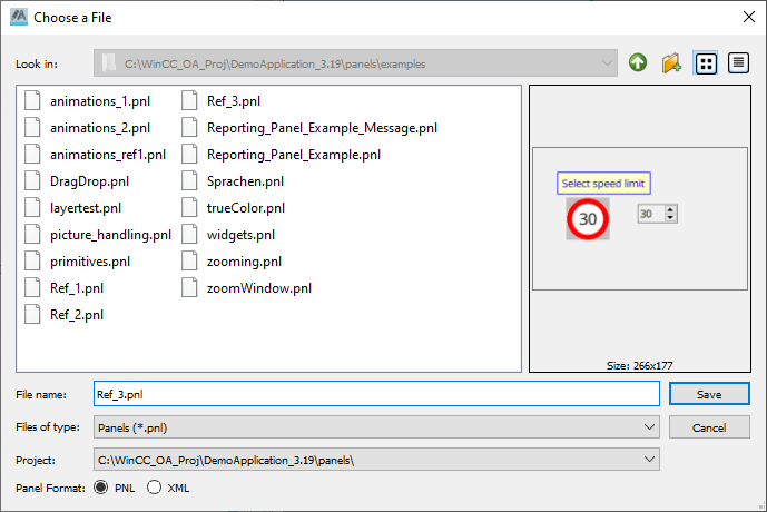
menu. The Choose A File selection dialog box opens.
Select the option Open panel from the Panel
menu. The Choose A File selection dialog box opens. -
Select a file and press the Enter key (or the Open button).
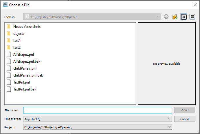
The Choose a file dialog box shows by default the \panels directory of the current project. You can create and open other sub-directories. In the figure above you can see the panels directory of the project.
On the right of the dialog box the preview and the size of the panel or image are shown. Note that the invisible objects of panels are not shown. Also note that panels can be viewed only in the panels directory and images only in the pictures directory.
Saving panels
The panel is saved as a file with the extension ".pnl" in the current project directory in the sub-directory /panels. If there is already a panel with the same name in the project directory, a dialog for overwriting the panel appears (Yes - Overwrites the panel, No - Dialog "Save as" is opened, Cancel - No action is executed).
To save a panel:
-
Select the Save panel option from the Panel menu or the button Save
 .
. -
When a panel is saved for the first time, the file selection dialog box Save as is shown:
-
Enter a new file name in the file selection dialog box.
-
Press the Enter key or click on Save.
-
Panels from Subprojects
When a panel from a subproject is saved, the save dialog for the panels opens. If the option "save" is selected, a dialog opens for selection where it shall be saved. The panel can either be saved back into the subproject or into the current project or the save can be aborted entirely.
To change panel file names
When saving panels for the first time, changing a file name or creating additional sub-directories, open the Save as file selection dialog by selecting "Save as" from the Panel menu.
Selecting Save Panel As Version you can save this panel in an older WinCC OA version.
In GEDI of an older WinCC OA version you can open this panel without restrictions. Note that some actual panel features are not supported in an older WinCC OA version (e.g. transparence). These conform to the possibilities of the older WinCC OA version automatically.
Saving references
The graphics editor GEDI in WinCC OA provides a facility for creating reference objects and re-using these as reference panels in other panels. The components linked in this way subsequently adopt every property change made on the reference object. By this means, for example, you can perform global replacements in all system diagrams simply by changing the original reference panel.
Reference panel files are saved with the file extension .pnl in the sub-directory.../panels/objects.
Create a reference panel
-
Open a new panel and draw a graphics object representing e.g. a red light. For example a red circular area with red lines as light rays.
-
Click on Save as in the Panel menu. In the file selection dialog box select the objects sub-directory and give this reference panel a name, for instance "RedLight". Click on the Save button.
View panel in runtime mode
Quicktest panel saves the currently loaded panel and then opens it in the Vision module.
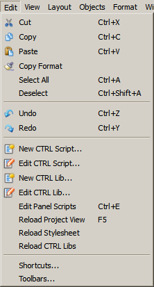
The Edit menu
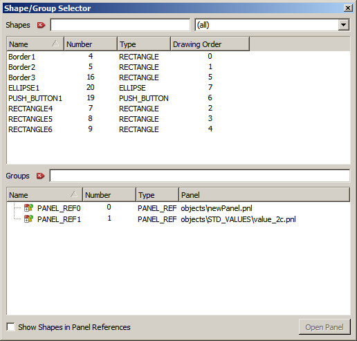
This menu contains generally familiar editing functions (Cut, Copy and Paste). Copy Format copies the format from one object to an other. You can also create a new CTRL script or a CTRL library. Reload Project View refreshes the project view. Reload Stylesheet reloads the design of the UI according to the used CSS file. Reload CTRL libs refreshes the CTRL Libraries. Select Shape/Group... opens the Select Shape/Shape Group/Panel Ref window (see second figure below), where you can select an object or an object group. The button Open Panel allows to directly open the selected (reference) panel. Use this window especially if you want to select an object inside a reference (see also chapter Properties of references and override). Shortcuts... opens the Edit Actions panel where you can define shortcuts for the functions of the graphics editor (see also the third figure below).
To copy a graphics object:
-
Select one or more graphics objects.
-
Select the Copy option from the File menu. The selected objects are copied to the clipboard.
-
Select Paste. The selected objects are inserted in the selected panel window, offset slightly down and to the right.
The View menu
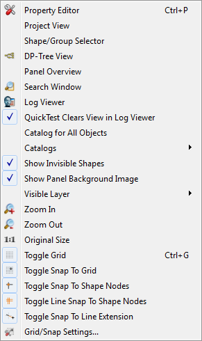
Property Editor
Opens the property sheet. See chapter Property Sheet.
Project View
Opens the project view. See chapter The project view.
Shape/Group Selector
Opens a panel for selecting shapes and groups where details like object type and drawing order are displayed. All elements are displayed and selectable with the exception of sub-shapegroups.
DP-Tree View
Opens the datapoint tree. See chapter PARA, basics.
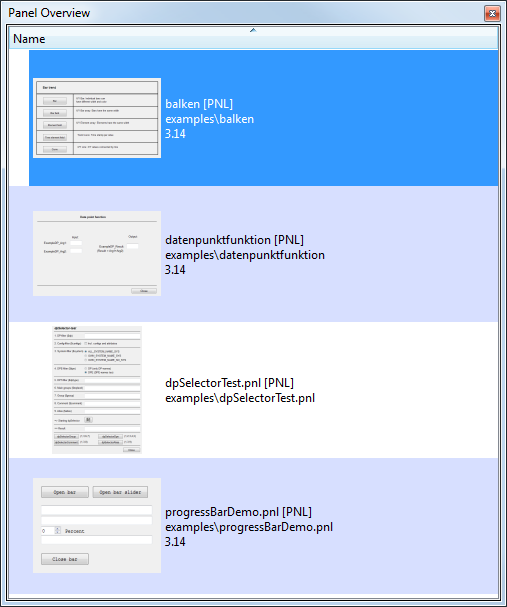
Panel Overview
Opens a list of all open panels and also displays a small preview of the panels as well as the following information:
-
Panel name (or file name if no panel name is defined) + panel format (XML or PNL)
-
Path including the file name
-
Project name of the sub project or installation (if the panel is from your project, nothing is displayed in this field)
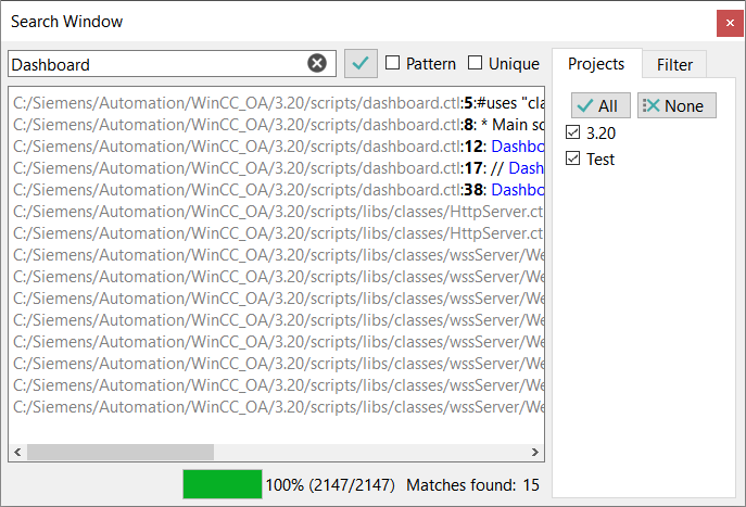
Search Window
This option opens the search window, which allows you to search for specific content. You can search either for the specific word or a pattern. The options to the side let you define the projects the search should include and the type of files that should be searched. The "bak" option will only become available when searching in panels is checked.
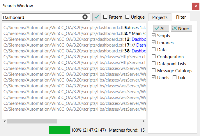
How to search in the Search Window
-
Select in the combobox right the file types which you want to search.
-
Tick the checkbox "Pattern", if you want to search for a pattern. The input is used as perl compatible regular expression in the search, see Qt QRegularExpression Class and regexpIndex().
-
Tick the checkbox "Unique", if you wish to see a file containing matching content only once.
-
Tick the checkbox "All Projects", if you want to search also in directories beyond your project directory.
-
Enter your search criterion into the input field on the left and start the search by clicking on the button
 .
. -
In the output window you can see all matches inclusive the directory path that include your search criterion.
-
The progress bar at the bottom of the window shows you when the search progress is finished (= 100%).
-
Secondly it informs you of how many matches were found.
-
To stop a search in progress, click the button
 .
. -
Double-clicking on a filename in the output window opens this file.
Note that wildcards like *zoom* cannot be used. "zoom" returns all panels and scripts with the content "zoom".
The search has a similar functionality to regexpIndex(), but uses the newer QRegularExpression Class instead of the QRegExp Class.
Extended Search Window (Find in Open Files)
The Search Window now includes the option to restrict the searches to currently opened files only.
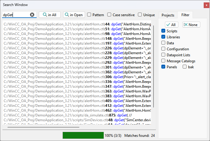
The window provides the following options:
- In All: Searches in all files according to the configured project level and filter settings.
- In Open: Searches only in all currently opened files.
- Case sensitive: Check this box to enables case-sensitive searching for both search modes.
When In Open Files is selected, the search ignores all other filtering options such as project levels or file type filters (panel, script, data, config, etc.). All opened files are searched regardless of their project location.
When In All Files is selected, the search respects the configured filters and project level settings of the Search Window.
All matches are listed in the result overview and highlighted directly in the corresponding files. Selecting a result automatically switches the focus to the related file.
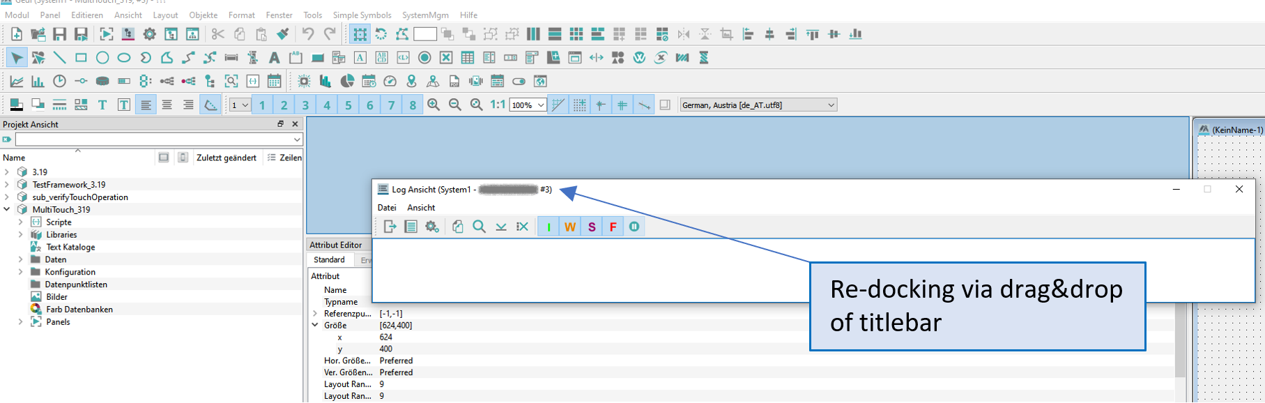
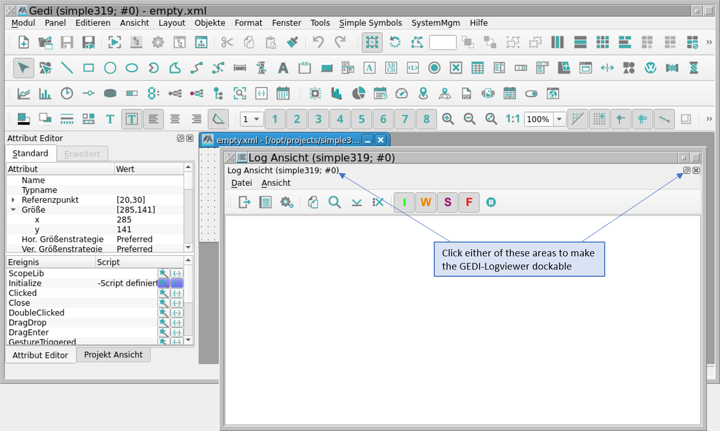
Log Viewer
QuickTest Clears View in Log Viewer
Clears all messages in the Log Viewer after a restart of the QuickTest. This function can only be used for the Log Viewer which is opened by the GEDI, not for the one which is opened by the Console.
Catalog for all objects
Opens the catalog with WinCC OA standard symbols. See chapter STD_symbols, basics.
Catalogs
Select here the WinCC OA object catalog C:\Siemens\Automation\WinCC_OA\[version] or the own reference objects from the project directory. See also STD_symbols, basics.
Show invisible shapes
Shows the invisible objects ("Visible" property in the property editor).
Show panel background image
Shows the background image of the panel (if specified).
Visible Layer
Show Layer 1 till Show Layer 8 shows the different layers of a panel.
Zoom in
Allows to zoom in the panel step by step.
Zoom out
Allows to zoom out the panel step by step.
1:1 Original (panel) Size
Resets the panel size to the original size.
The alignment of objects may slightly change if the zoom level is adjusted. This has to be considered when drawing panels in a different zoom level than the actual zoom-level of the end user.
Toggle Grid
Hides the grid lines.
Toggle Snap To Grid
Enables/disables grid points as snap points.
Toggle Snap To Shape Nodes
Enables/disables the snap points of shapes (corner points and center points). This option helps e.g. to connect a drawn line exactly to the corner point of an object.
Toggle Line Snap to Shape Nodes
Enables/disables reference lines to the snap points on the outlines of shapes (left, right, up, down, middle) in order to ease the alignment of objects.
Grid/Snap settings...
Opens a window where you can specify grid and snap settings. See chapter The panel window.
The Layout menu
This menu helps to arrange the graphics objects in the panel.
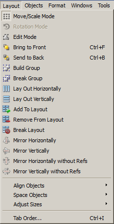
| Icon | Function |
|---|---|
|
|
Switch to move/scale mode. (you can move an object). |
|
|
Rotate object with the mouse. You can rotate an object freely. You can specify the rotation angle also in the property sheet. Entering +90 degrees rotates the object anticlockwise. Entering -90 degrees rotates the object in a clockwise direction. By selecting 0 degrees, the object is returned to its original position. After rotation, the option shows the current angle of rotation for the object. A Snap to every 45 degrees via Shift key is now possible. If objects are rotated, truncation errors can arise. Note Only simple graphics objects can be rotated (except for the frame). Rotation is not possible for complex graphics objects. |
|
|
Edit Points, edit contours (corner points of polygons, curves). You can use this function to show the (black) curve edit points on polylines and freehand lines (see Freehand line and polygon ). You can change the shape or contour of the curve by clicking on and dragging these black points. To disable the editing mode, select the move or scale mode (the first option of this menu) again. |
|
|
Raise and lower objects (brings the object right to the front or sends the object right to the back). |
|
|
Build Group. Grouping of selected graphics objects and/or references. Clicking an object, which is a member of the group, selects the whole group automatically. This behaves like an individual object, i.e. resizing or moving have an effect on the whole group. Thus you may build upper-level groups included already existing groups as often as you need. In the property sheet you can name your group. The built groups are via this name addressable (using setValue()/getValue(), but not with <grouName>.<graphicFunctionName>()). The addressability of the individual objects and low-level groups still persists. Graphics objects (groups of) may be combined with references (groups of) arbitrary. Any edit steps can be undone as long as the group hasn't been broken. So after a group has been built it isn't possible to undo to the broken state of the group. |
|
|
Break Group. Breaks a built (upper-level) group into its objects. |
|
|
Mirrors one or multiple selected objects horizontally or vertically. All WinCC OA objects can be mirrored, whereas a frame, all widgets, primitive texts change only their position and the text can still be read from left to the right. A mirroring can be undone or redone, however, this must be done for each object separately (this means that if several objects are selected, also several steps back/forward are necessary). Panel references can also be mirrored. Thereby for each shape of a reference an override (transformation) is created. Also here undo and redo actions must be done separately. Fill patterns (pixmaps) are not mirrored automatically together with the object. |
|
|
|
|
|
These actions allow mirroring one or more selected objects horizontally or vertically, whereby references are moved only across the mirror axis. I.e. in contrast to the known mirroring of objects, references will not be turned upside down, but are moved to the opposite side of the mirror axis with the same distance to this. The move is a single operation, i.e. the reference can be moved with one undo click to the old position. If multiple objects have been mirrored, an undo click must be performed for each object individually. |
|
|
|

|
Forms a horizontal layout around the selected objects or the whole panel. |

|
Forms a vertical layout around the selected objects or the whole panel. |

|
Adds a selected object to the selected layout. |

|
Removes a selected object from the selected layout. |

|
Breaks the selected layout. |
|
Align objects Space objects Adjust sizes |
Aligns objects (left, right, horizontally centered, vertically centered, top, bottom).
Spaces objects horizontally or vertically or space by distance (the distance is given in pixels). 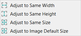
Changes the size of the objects based on the object size of the first selected object. The "Adjust to Image Default Size" option will resize all selected fillable primitive graphic objects that use an image as "fill" to the default size of the image (e.g.: pixel size for "png" files etc, but also using the defined size of vector graphics (svg, wmf)). This option is also available as a context menu when right-clicking on a fillable primitive graphic object with an image as "fill". Note:
For the alignment of objects the size of the used border frame is also added to the calculation. If two objects
have the same width and other values but a different border size their alignment is not identical. |
| Tab Order... | Opens the "Define Shape tab order" window (see figure below) where you can specify the tab order for each object. |
When mirroring a graphic object, the fill is NOT mirrored.
To rotate a graphics object using rotation mode
-
Select the graphics object.
-
Select the Rotation mode option.
-
Pick one of the corner points of the object and drag this using the mouse in a circular path to the final position required. The actual angle of rotation is shown in a text field.
-
Releasing the mouse button then fixes the object in the new, rotated position.
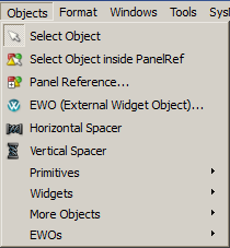
The Object menu
The functions in the Object menu are used for creating graphics objects. See also chapters Simple graphics objects and Complex graphics objects.
NOTE
The menu options match the buttons in the Object icon bar, and are described in more detail in the chapter Creating graphics objects.
To find out which graphics objects can be created, see chapters Simple graphics objects and complex graphics objects.
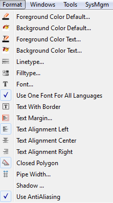
The Format menu
The Format menu allows to format the graphics objects like set the background and foreground color, specify the line type etc.
| Icon | Function of the "Style icon bar" buttons |
|
|
Set the foreground color of an object. |
|
|
Se the background color of an object. |
|
|
Set the foreground color of a primitive text. |
|
|
Set the background color of a primitive text. |
|
|
Set the line width and style. |
|
|
Set the fill type (outline, solid, pattern, hatch). |
|
|
Font style, font size, bold, italic. Sets the default font for all new objects. See Font selection in GEDI. |
|
- Use One Font For All Languages |
Uses the currently selected font for all languages. By default this setting is active. I.e. if the font (see option above) is set to bold and e.g. a frame is added to a panel, by default the frame title is displayed in the selected font and bold for every project language. If for example the selected font should still be used for all texts as the default font, but for example only the frame title shall be displayed italic in English language, the language in the GEDI online language switching must be set to English and following the font must be set to italic in the Attribute editor of the frame. To apply the now selected font for the frame title in English (italic) to the other project languages the context menu option "Apply To All Languages" of the "Font" attribute can be used. If this option is disabled and, for example, a frame is added to a panel and at this point of time the font is set to italic, this font will be applied only to this language, which is currently active in the GEDI online language switching. For all other languages the frame title is shown in this font, which is selected in the font option (Format -> Font) for the explicit language from the GEDI online language switching at this moment. To use different fonts for the languages of multilingual project, this option must be disabled. Note: This option does not update the already existing texts to a particular font. This means that if this option is disabled while e.g. a frame is added to a panel and afterwards the option will be enabled, the font of the frame title will not the applied from the current language to the other languages. Use the context menu option in the Attribute editor described above. |
|
|
Text with border. |
|
|
Left-aligned, centered, right-aligned. |
|
|
Specifies whether a polygon should be closed or not. If you select this option, the polygon is open. The default would be closed. |
|
|
The default width for a pipe. In order that the width for a pipe does not need to the set separately for each drawn pipe ("width" attribute in the Attribute Editor), with this option a fix width in pixel can be set. This will be applied to all new drawn pipes - the width of the pipes that already were drawn will not be changed. |
| Shadow | Opens the panel to define the shadow settings (color, radius). |
| Use AntiAliasing | If you activate anti-aliasing, it is used for all objects except of frame, primitive text and rectangle. |
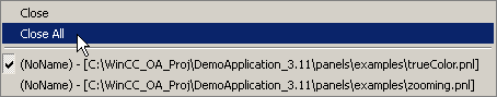
The Window menu
Here you can set the order of the panel windows, and close open windows.
The Tools menu
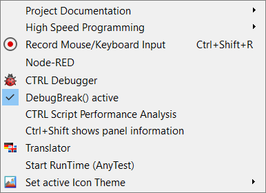
The tools menu provides the following options:
- Project Documentation: The option opens the Project Documentation menu.
- High Speed Programming: Opens the High Speed Programming menu
- Node-RED: This opens the Node-RED Wizard.
- CTRL Debugger: Starts the CTRL debugger.
- DebugBreak() active: Defines if the break points are active that have been set using the function DebugBreak().
- CTRL Script Performance Analysis: Opens the performance analysis panel for CTRL Scripts.
- CTRL+Shift shows panel information: Activates or deactivates the UI_INFO debug flag, see General debug flags
- Translator: Opens the WinCC OA translator. Note that this entry is only available if the project is multilingual. For more information see Translator.
- Start RunTime (<project_name>): Starts the startup panel (vision/startup.pnl). By default this opens the login panel (can be customized in the panel script of the startup panel). This option is equivalent to the options "-p vision/startup.pnl -iconBar -menuBar" of a UI manager, but the UI manager must not be started.
- Set active Icon Theme: The option allows you to set any of the available Icon Themes at runtime.
The icons changed at runtime are not changed in the already opened modules. Only when a new module is opened, will the chosen Icon Theme be applied there.
The SysMgm menu
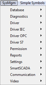
This menu is used for managing the WinCC OA system. Please refer to System management for further information
The Simple Symbols menu
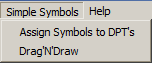
The tools menu provides the following options:
-
Assign Symbols to DPT's: Opens the panel to establish a direct connection between the created symbol and the corresponding data point type i
-
Drag'N'Draw: With this panel the symbols that have been configured with the assignment panels can be inserted.
The Help menu
The Online Help for WinCC OA can be opened via the Help menu.
The first option in the Help menu opens the start page of the Online Help for WinCC OA.
You will find the reference document for the Graphical Editor GEDI module under GEDI Module.
Similarly the Online Help for the VISION Module is accessed under Vision Module, and the Help manual for the PARA module under Para Module.
Control Programming contains the reference document for control programming.
About QT shows you information about the QT toolkit on which the WinCC OA user interface is based.
About WinCC OA shows you the ETM address information and the currently used WinCC OA version (version + patch)..